background image

2


MANUFACTURER: Whalen Furniture Manufacturing 
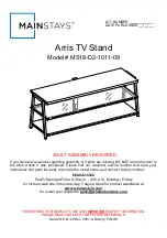
CATALOG: Arris TV Stand  
MODEL # MS18-D2-1011-09 
MADE IN CHINA 


1.  Please read the Assembly Instructions prior to assembling this product. 
2.  Remove all hardware from the box and sort by size. 
3.  Check to see that all hardware and parts are present BEFORE assembling. 
4.  Ask a friend to assist you with the assembly of this furniture. 
5.  To avoid damage, assemble the product on a sturdy, level and protective surface. 
6.  Please wait until all steps are completed before fully tightening Bolts. 
7.  Make sure all Bolts are tightly fastened before the unit is used. 


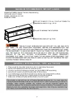
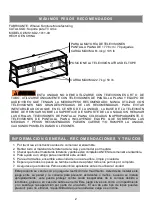
M A X I M U M   R E C O M M E N D E D   W E I G H T   L O A D S  

FITS UP TO MOST 177.8 cm / 70 in FLAT PANEL TVs 
MAXIMUM LOAD 61.3 kg / 135 lb


MAXIMUM LOAD 22.7 kg / 50 lb


G E N E R A L   I N F O R M A T I O N ,   T I P S   a n d   T R I C K S  

This  product  is  sold  with  one  set  of  Tipping  Restraint  Hardware  Kit.  You  must  install  the 
Tipping Restraint Hardware  between the  wall and the TV stand to  prevent any  accidents or 
damages.  When  properly  installed,  this  restraint  can  provide  protection  against  the 
unexpected tipping of the unit due to small tremors, bumps or climbing. The restraint is only a 
deterrent  and  is  not  a  substitute  for proper  adult  supervision.  Use  of  tip-over  restraints  may 
only reduce, but not eliminate, the risk of tip-over. 

THIS UNIT IS NOT INTENDED FOR USE WITH CRT TVS. USE ONLY WITH 

FLAT  PANEL  TVS  AND  AUDIO/VIDEO  EQUIPMENT  MEETING  RECOMMENDED  SIZE  AND 
WEIGHT  LIMITS.  NEVER  USE  WITH  LARGER/HEAVIER  THAN  RECOMMENDED  FLAT  PANEL 
TVS OR EQUIPMENT. TO AVOID INSTABILITY, PLACE FLAT PANEL TV IN THE CENTRE OF THE 
UNIT;  THE  BASE  OF  THE  TELEVISION  MUST  BE  ABLE  TO  REST  ON  THE  SUPPORTING 
SURFACE  OF  THE  UNIT  WITHOUT  OVER-HANGING  THE  EDGES.  IMPROPERLY 
POSITIONED FLAT PANEL TVS, OR FLAT PANEL TVS INCLUDING OTHER EQUIPMENT THAT 
EXCEED RECOMMENDED SIZE AND WEIGHT LIMITS COULD FALL OFF OR BREAK THE UNIT, 
CAUSING POSSIBLE SERIOUS INJURY. 

PLACE TV BEHIND THE STOPPER 

Summary of Contents for MS18-D2-1011-09

Page 1: ...arts are missing DO NOT return this item to the store where it was purchased Please call our customer service number and have your instructions and parts list ready to provide the model name part name...

Page 2: ...nstall the Tipping Restraint Hardware between the wall and the TV stand to prevent any accidents or damages When properly installed this restraint can provide protection against the unexpected tipping...

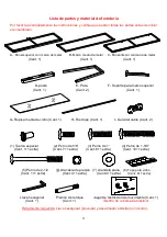
Page 3: ...Qty 2 F Top Frame Support Qty 1 G Middle Glass Shelf Qty 1 H Stop Rail Qty 1 I Cable Wheel Qty 2 1 Flange Nut 2 5 8 Bolt 3 1 Bolt 4 1 5 8 Bolt Qty 1 1 extra Qty 7 1 extra Qty 6 1 extra Qty 10 1 extra...

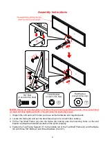
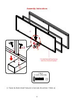
Page 4: ...2 Locate the Spine D and set the back face down on a scratch free surface 3 Fit the Top Shelf Frame A onto the Spine D making sure the mounting holes on the end bracket overlap the threaded sockets on...

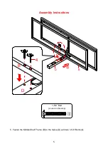
Page 5: ...5 Assembly Instructions 5 Fasten the Middle Shelf Frame B to the Spine D with two 1 5 8 Bolts 4 1 5 8 Bolt 2 used in this step D 4 B D B...

Page 6: ...6 Assembly Instructions 6 Fasten the Bottom Shelf Frame C to the Spine D with two 1 Bolts 3 3 C D D C 1 Bolt 2 used in this step...

Page 7: ...f Frames A and B with four 1 5 8 Bolts 4 8 Fasten the Leg E to the Bottom Shelf Frame C with two 1 Bolts 3 9 Repeat the same procedure to attach the other Leg E at the opposite side 1 Bolt 4 used in t...

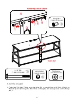
Page 8: ...e Spine D by inserting one 2 1 2 Bolt 5 with the Washers 6 and 7 through the drilled holes on the spine and securely screw into the Flange Nut 1 A D 6 7 5 1 A D 2 1 2 Bolt 1 used in this step Flange N...

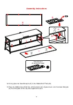
Page 9: ...the Glass Bumpers 8 on the Middle Shelf Frame B 13 Place the Middle Glass Shelf G with the black side of glass down onto the Glass Bumpers 8 Push the glass all the way back against the spine Glass Bum...

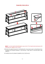
Page 10: ...s I to the backside of the Spine D with the 5 8 Bolts 2 Tighten the bolts with enclosed 4 mm hex wrench NOTE You can use the cable wheels to help keep your entertainment center s cables and cords orga...

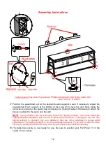
Page 11: ...ng your flat panel television directly on the console 15 Remove the paper backing from the Stop Rail H then properly align the Stop Rail with the top edge of the stopper template on Top Panel A Press...

Page 12: ...ip over restraint to the spine and the wall NOTE Young children can be seriously injured by tipping furniture You must install the Tipping Restraint Hardware with the unit to prevent any accidents or...

Page 13: ...furniture in a climate controlled environment Extreme temperature and humidity changes can cause fading warping shrinking and splitting of wood It is advised to keep furniture away from direct sunligh...

Page 14: ......

Page 15: ...ante no retorne este producto a la tienda donde lo compr Por favor llame a nuestro departamento de ayuda al cliente teniendo su instructivo y lista de partes para proveer el modelo nombre de parte o e...

Page 16: ...stalar este juego entre su pared y la consola para prevenir accidentes o da os Cuando se instala apropiadamente este puede protejer contra caida inesperadas de la consola debido a temblores golpes o e...

Page 17: ...1 G Repisa media de vidrio Cant 1 H Riel tope Cant 1 I Gu a del cable Cant 2 1 Tuerca especial 2 Perno de 5 8 3 Perno de 1 4 Perno de 1 5 8 Cant 1 1 extra Cant 7 1 extra Cant 6 1 extra Cant 10 1 extr...

Page 18: ...ensamble de poste D y ponerlo boca abajo en una superficie libre 3 Coloque el panel superior con marco de metal A sobre el ensamble de poste D asegur ndose de que los orificios de montaje en el sopor...

Page 19: ...5 Instructivo de ensamble 5 Sujetar el marco de repisa medio B al poste D con 2 pernos de 1 5 8 4 D 4 B D B Perno de 1 5 8 2 usados en este paso...

Page 20: ...6 Instructivo de ensamble 6 Sujetar el marco de repisa inferior C al poste D con 2 pernos de 1 3 3 C D D C Perno de 1 2 usados en este paso...

Page 21: ...a A y B con 4 pernos de 1 5 8 4 8 Sujetar la pata E a marco de repisa inferior C con 2 pernos de 1 3 9 Repetir el mismo procedimiento para adjuntar la otra pata E en el extremo opuesto Perno de 1 4 us...

Page 22: ...un perno de 2 1 2 5 y las arandelas 6 y 7 a trav s de los agujeros perforados en el poste D y luego hacia la tuerca especial 1 A D 6 7 5 1 A D Perno de 2 1 2 1 usados en este paso Tuerca especial 1 us...

Page 23: ...vidrio 8 en el marco de repisa media B 13 Colocar la repisa de vidrio G con la parte del vidrio negro hacia abajo sobre los topes de para vidrio 8 Empujar el vidrio todo el camino contra el poste Top...

Page 24: ...a parte posterior del poste D con los pernos de 5 8 2 Apretar los Pernos con la llave hexagonal de 4 mm NOTA Usted puede usar las gu as de cable para mantener los cables del centro de entretenimiento...

Page 25: ...levisi n de pantalla plana directamente sobre la consola 15 Retirar el papel protector del riel tope H luego alinear el tope con el recorte del templete del tope de acr lico en el panel superior A Emp...

Page 26: ...tricci n de movimiento para adjuntar los topes de movimiento al poste y a la pared NOTA Ni os peque os pueden resultar lastimados por muebles inclinados Debe instalar el juego de restricci n de movimi...

Page 27: ...ue se contraigan o que la madera se raje Es recomendable mantener la unidad lejos del sol directo ya que puede da ar el acabado Cuidados adecuados y limpieza pueden extender la vida til de su unidad S...

Page 28: ......

Reviews: