background image


IT 


13 


fasten the motor cable connector to the control unit. (Plug 1) 


Fix the cables to the inner walls of the machine compartment so that they do not interfere in the 
movement of the machine elements. 

6.


Testing the correct operation of the machine by acting on the remote control or on the control box. 
Make sure, before you do, that there are no persons or property which could be harmed. 

7.


Install  the  adjustable  support  column  ④  ⑤  interface  by  means  of  4  M5  screws  provided.

NOn 

tightening the screws, so as to facilitate the subsequent step of alignment between the cover panel 
and floor. 

8.


The interface VESA ⑥ vertical position, and then the TV, can  be adjusted by sliding the VESA ⑥ 
interface along the interface ④ column. In order 

to determine the height at which you want to fix 

the VESA interface, it is necessary to evaluate the following elements: 

o


Distance between VESA (the TV fixing points) and bottom of the TV frame (depending on the 
TV model and should therefore be measured). 

o


A completely closed column must remain at least 2 cm of free space between the base of 

the machine and the frame ① bottom of the television or any appendices below the same 

which could increase the encumbrance

1

o


Location of the cover panel with respect to the upper frame of the TV: adjacent to the same 
or slightly spaced. 

9.


Loosen  the  4  M6  screws  that  secure  the  VESA  interface  interface  ⑥  ④  column.  Turn  the  VESA 
interface ⑥ preset height and tighten the screws.


10.


Install the TV (screws not provided) to the 

VESA ⑥ using all 4 fixing points.


11.


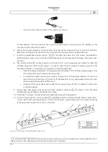
Install the cover panel. To this end the ⑤ adjustable support includes through holes 8 and 8 slots 

4 from right to left with development, 4 from front to back - which allow to cure to better centering 
of the panel with respect to its seat on the floor. 


Figure 9: Punctures of the adjustable support 


1


In the case of the machine reset procedure (see Section 3.6) the column is closed for further 5-6 mm compared to the normal configuration and it is 

necessary to leave a certain margin of safety to avoid possible collisions of the TV with the base.


Summary of Contents for Levante

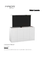
Page 1: ...Maior Levante Instruction Manual Rev 1 0 05 2019 Eurotecno srl Via Proventa 120 1 48018 Faenza RA Italy Tel 39 0546 646821 info maiormover it...

Page 2: ...ADDRESS MAIOR EUROTECNO SRL ADDRESS Via Proventa 120 1 48018 Faenza RA Italy Tel 39 0546 646821 DOCUMENT TYPE Instruction Manual PRODUCT Levante YEAR OF CONSTRUCTION 2019 CONFORMITY...

Page 3: ...maintenance must know the location and be able to consult it at any time Please refer to our latest version of the manual here https www maiormover it area riservata All machines are subjected to test...

Page 4: ...2 Assembly instructions 11 2 1 General safety instructions 11 2 2 Installation 11 2 2 1 Instructions and tips for creating mobile 11 2 2 2 installation Steps 12 3 Operation use maintenance and disposa...

Page 5: ...also envisaged that the environment in which it will be placed this mobile is not subject to jolting movements or that may affect the cabinet and or the machine installed in it The machine provides fo...

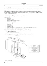
Page 6: ...ine check the contents of the crate The box contains 1x machine 1x Drilling template 1x adjustable stand for top panel 2x decorative covers 2x Side cover 1x unit 1x Receiver Push button 1x 1x Ethernet...

Page 7: ...ond to that listed above in the case when ordering both a different configuration was requested 1 3 2 Identification of the machine Each machine is accompanied by a label that uniquely identifies by s...

Page 8: ...um Total weight kg 33 Electrical system Power circuit V 220 110 Frequency Hz 50 60 flow Maximum TV Capacity including accessories kg 30 Maximum TV Size 65 900mm or until the short side Maximum coverin...

Page 9: ...C approved system in accordance with EN 60335 1 UL 962 with CBD6S Figure 4Column DL12XL 1 3 5 motor lead Figure 5 Motor lead The motor must be connected to the control unit via the supplied cable The...

Page 10: ...1 3 7 Power cable compatible EU version Figure 7 Alimentation cable 1 3 8 RFRL Receiver The RFR receiver operates radio frequency to 433 MHz It is connected to the control unit through a cable with a...

Page 11: ...to be dedicated to only one slot of the TV as well as provided with doors drawers shelves 2 2 1 Instructions and tips for creating mobile For the furniture planning no special specifications Follow t...

Page 12: ...the base by using all 6 provided screws UNI EN ISO 10642 4 Attach to the structure of the cabinet where appropriate the control unit and RF receiver See Figure 8 5 Make the appropriate electrical con...

Page 13: ...the TV model and should therefore be measured o A completely closed column must remain at least 2 cm of free space between the base of the machine and the frame bottom of the television or any appendi...

Page 14: ...chine showing the continuous plane 12 Screw to the adjustable support sides of the lateral coverages exploiting the provided M3 screws supplied 13 Carry out the necessary connections audio and video p...

Page 15: ...or exert a force on the column or on the TV EUROTECNO SRL accepts no responsibility for property damage and or injury caused by failure to comply with these instructions 3 2 commands Maior Levante ca...

Page 16: ...imum extension B Press and hold the B button for the descent of the screen Releasing the button stops the column in position If you keep the key pressed the column stops at the maximum closing automat...

Page 17: ...the machine television and added devices The door catenary cables does not flow regularly in its housing Check the integrity of the catenary Check and remove the causes of friction Allow completely fr...

Page 18: ...ed through any of the above commands 3 7 Maintenance The Maior Levante does not require any kind of routine or additional maintenance 3 8 Demolition and disposal For the demolition and disposal of the...

Page 19: ...IT 19 4 Attached documentation 4 1 EC Declaration of Conformity Each machine is attached its own CE compliance documentation Check the lamp among the documents annexed...

Reviews: