background image

MIEN2016/2018/2024/2026 Rack Mount Industrial Ethernet Switch

- 7 -

Figure 2-5 Schematic diagram of the installation dimensions of MIEN2016 and

MIEN2024

The installation dimensions of MIEN2018-2S/M and MIEN2026-2S/M are

shown in Figure 2-6.

Figure 2-6 Installation dimensions of MIEN2018-2S/M and MIEN2026-2S/M

For most industrial applications, 19-inch rack installation is very

convenient. The installation situation of the rack should be checked before
installation. It mainly includes the following two contents:

Is there enough space for installing this product

Is there a power supply suitable for the work of this product

When installing, first determine the installation position of the product,

align the mounting holes of the switch with the holes on the rack, and fix it with
4 screws. The recommended specification is M5*14.

2.2.3. Cable connection

After the correct installation, the cables can be installed and connected,

mainly including the cable connections of the following interfaces.

Working interface

Summary of Contents for MIEN2016

Page 1: ...MIEN2016 2018 2024 2026 Rack Mount Industrial Ethernet Switch User Manual Edition V2 0 Wuhan Maiwe Communication Co Ltd ...

Page 2: ...his manual does not represent for corresponding authorization on these information Our company attempts to ensure the accuracy and applicability for the information provided in this manual however our company does not assume any responsibility for the use of these information and does not assume any joint responsibility for the use of these information There may be a few technical or typographical...

Page 3: ...ected with each other frequently inspection is needed Please keep the fiber socket and plug clean Do not look directly at the fiber section when the equipment is working Please keep the equipment clean and wipe it with a soft cotton cloth if necessary Please do not repair the equipment by yourself unless there is clear instructions in the manual Under the following circumstances please cut off pow...

Page 4: ... Description 3 2 1 Hardware structure 3 2 1 1 System structure 3 2 1 2 Whole machine structure 3 2 2 Hardware installation 5 2 2 1 Installation requirements 5 2 2 2 Host installation 6 2 2 3 Cable connection 7 2 2 4 Fiber optic connection 8 2 2 5 Laying cables 8 2 3 Simple test 9 2 3 1 System self check 9 2 3 2 Copper port test 10 2 3 3 Fiber port test 10 3 Maintenance and Service 12 3 1 INTERNET ...

Page 5: ...he switch uses rack installation This series of industrial Ethernet switches has a total of 26 100M ports at most and its switching bandwidth is 8 8G They all support 8K entries in the MAC address table 1 2 Characteristic 1 2 1 Industrial network performance Broadcast storm suppression Optional 100Base FX with different transmission distances and different types of optical fiber interfaces Store a...

Page 6: ...nt network information exchange capabilities Technical index IEEE standard 802 3 802 3u 802 3x Exchange method store and forward Exchange bandwidth 8 8G Flow control full duplex flow control half duplex back pressure control MAC address 8K Transmission distance twisted pair cable 100m fiber 100Mbps maximum 20 40 60 80km Broadcast storm real time broadcast storm suppression EMC standard EN61000 4 2...

Page 7: ...per ports and serial ports have EMC protection 2 1 2 Whole machine structure The chassis is a 19 inch 1U rack structure as shown in Figure 2 1 the whole machine adopts a six sided fully enclosed structure Abandon the traditional flow fan heat dissipation form reduce the power consumption of the whole machine but also improve the stability of the system The dimensions are 482 6 44 210mm Figure 2 1 ...

Page 8: ...ST or FC Optical fiber interfaces need to be used in pairs TX and RX are a pair TX port is the optical transmitting end connected to the optical receiving end RX of the optical interface of another remote switch RX port is the optical receiving end connected to the same optical interface of the same remote switch The optical transmitter TX The 100M fiber interfaces mainly include SC ST FC As shown...

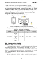
Page 9: ... 4 Schematic diagram of power input terminal The power requirements of this series of switches are shown in Table 2 2 Table 2 2 Switch power requirements Voltage voltage range Operating temperature Storage temperature Humidity 220VAC DC 85 265 VAC 47 63Hz or 110 370 VDC 40 C 85 C 40 C 85 C 5 95 2 2 Hardware installation 2 2 1 Installation requirements The industrial Ethernet switch is a single str...

Page 10: ...aximum current allowed by lines of different widths If the current exceeds the maximum rated current the wire will overheat and cause serious damage to the equipment At the same time you must also pay attention to the following Separate the paths of power lines and equipment lines If the two paths must cross make sure that these lines are perpendicular at the intersection It is not allowed to lay ...

Page 11: ... situation of the rack should be checked before installation It mainly includes the following two contents Is there enough space for installing this product Is there a power supply suitable for the work of this product When installing first determine the installation position of the product align the mounting holes of the switch with the holes on the rack and fix it with 4 screws The recommended s...

Page 12: ... a transmission distance greater than 60km do not use short optical fibers below 20km to connect so as not to cause the optical saturation and overpower at the receiving end of the module to burn The steps to connect the pluggable fiber optic module are as follows Remove and keep the rubber sleeve of the LC SC or FC port When not in use put on a rubber sleeve to protect the fiber terminator Check ...

Page 13: ...the cables power cords and ground wires cannot be overlapped or mixed When the cable is too long the cable must be neatly placed in the middle of the cable rack and cannot be pressed on other cables When laying pigtails prevent the optical cable from knotting and minimize the turning points and the turning radius should not be too small The lashing should be moderately tight and not too tight When...

Page 14: ... the test computer through a direct connected network cable and PING commands are sent to each other and both parties can correctly PING to each other without packet loss At the same time the LINK ACT light corresponding to the optical port should be on It means that the hardware of the two fiber ports under test is working normally and the other optical ports are tested in the same way Figure 2 8...

Page 15: ...r of bytes to send data packets t refers to continuously sending data run ping 192 168 0 10 l 1000 t in test computer 2 in the same way If test computer 1 returns Reply from 192 168 0 11 bytes 1000 time 10ms TTL 128 test computer 2 returns Reply from 192 168 0 10 bytes 1000 time 10ms TTL 128 use CTL after running for more than 10 minutes The C command statistics packet loss rate is 0 indicating th...

Page 16: ...ement 3 1 INTERNET service Through the technical support section of Maiwe website you can get more useful information and usage skills 3 2 Technical support telephone service Users who use the products of Wuhan Maiwe Communication Co Ltd can call the technical support office of Maiwe Maiwe has professional technical engineers to answer your questions and help you in the first time to solve the pro...

Page 17: ...4 2026 Rack Mount Industrial Ethernet Switch 13 Our company has the right to change the product model without notifying the user For the latest information please consult our company s market or technical support staff ...

Page 18: ... MAIWE COMMUNICATION CO LTD Add Building 2 Area E Phase ii Optical valley core center No 52 Liufang road East Lake Hi tech Development Zone Wuhan China Phone 027 87170215 16 Fax 86 027 87170217 www maiwe com ...

Reviews: