background image

MISCOM7028GX/MISCOM8028GX Series Industrial Ethernet Switch

- 13 -

10/100/1000Based-TX. Connect the terminal equipment with straight line cable,
connect the network equipment with cross-over cable.

Connecting network managed port

The CONSOLE port of the product can be connected to the serial port of

the control computer.

Connecting power

After all other cables have been connected, then connect the power

supply that meets the product specifications.

3.4. Laying Cables

Laying cables should be compliance with the following items:

Check whether the specifications, model and quantity of all cables are

consistent with the construction drawing design and contract requirements
before laying the cables.

Before the cable is laid, check whether the cable is damaged, whether

there are quality certificates such as the factory record and quality assurance.

The specifications, quantity, routing direction, and placement position of

the required laying cables should meet the construction drawing design
requirements. The laying length of each cable should be determined according
to the actual location.

User cable and power cable should be placed separately.

There MUST be no disconnection in the middle of the laying cable, or a

connector in the middle.

The cable should be straight and neatly discharged in the aisle, and the

curve should be even, smooth and straight.

The cable should be straight in the channel, and should not exceed over

the channel, block other access holes, and should be tied and fixed at the
cable exit channel or cable bend.

When the cables power cables and ground cables are placed in the

same slot, the three types of cables cannot overlap and mix. If cable is too long,
the cable grounding plate must be placed in the middle of the cable tray, and it
cannot be pressed on other cables.

Prevent the cable from knotting, reduce the bend and avoid small bend

radius when laying the fiber on the tail. The lashing should be tight and not too
tight. When placed on the cable tray, it should be placed separately from other
cables.

The two ends of the cable should have corresponding identifiers. The

content of the identification should be concise and easy to maintain.

Attention:

Summary of Contents for MISCOM7028GX Series

Page 1: ...MISCOM7028GX MISCOM8028GX Series Industrial Ethernet Switch User Manual Edition V1 1 Wuhan Maiwe Communication Co Ltd...

Page 2: ...formation provided by our company in this manual does not represent for corresponding authorization on these information Our company attempts to ensure the accuracy and applicability for the informati...

Page 3: ...ted with each other frequently inspection is needed Please keep the fiber socket and plug clean Do not look directly at the fiber section when the equipment is working Please keep the equipment clean...

Page 4: ...gn 2 1 3 Packing List 3 2 Interface Instructions 4 2 1 Indicator Lights 4 2 2 Ethernet RJ45 Port 5 2 3 SFP FX Port 7 2 4 CONSOLE Port 8 2 5 Relay Port 8 2 6 Power Port 9 2 7 Ground 10 3 Hardware Insta...

Page 5: ...s to switch Telnet management system SNMP management software and other network monitoring protocols such as LLDP SNTPv4 and DHCP This layer 3 Industrial Ethernet Switch also supports multiple advance...

Page 6: ...Support full duplex and half duplex mode flow control Reliability MTBF 50 000 hours Support power alarms port alarms and ring alarms FTP TFTP based online software upgrade allowing users easily manage...

Page 7: ...item in the list is lost or damaged please contact the distributor or MAIWE s customer service center they will assist you to make replacement or complement Items Quantity MAIWE Brand Managed Switch...

Page 8: ...LINK ACT 1 24 X1 X4 SPEED 1 24 X1 X4 Red light on Green light off Green light periodically flashes Green light periodically flashes Green light on Green light flashes Green light on Green light off Po...

Page 9: ...s feature If the equipment connected to these ports does not support adaptive function the port will force itself to work at the same rate as the other parties avoiding full half duplex mismatch the t...

Page 10: ...Number MDI X Signal Name MD Signal Name 1 Transmit receive data TRD1 Transmit receive data TRD0 2 Transmit receive data TRD1 Transmit receive data TRD0 3 Transmit receive data TRD0 Transmit receive d...

Page 11: ...er cable connection method Note Cable colors definition in the picture meet EIA TIA568B Standard 2 3 SFP FX Port The Gigabit FX port of the switch is 1000Base LX full duplex single mode multi mode FX...

Page 12: ...ncy recovery time is less than 20ms which can effectively improve the reliability of network operation SFP module as below picture SFP module 2 4 CONSOLE Port CONSOLE port is a RJ45 port refer to belo...

Page 13: ...is power failure port link is down or network storm occurs the NO relay is open and the NC relay is closed The relay recommended switch load capacity is 1A 24VDC Alarm delay diagram 2 6 Power Port Th...

Page 14: ...the other end of the grounding wire to the ground reliably The grounding wire cross section is not less than 2 5 Important notes Power on operation Connect the power supply cable with terminal blocks...

Page 15: ...strong electromagnetic interference Standard 19 U rack mountable installation Check for suitable cables and connectors Attention Make sure the power cable is disconnected before installing or connect...

Page 16: ...Mainframe picture as below Mainframe picture For most industrial applications it is very convenient to install in a 19 inch rack Check the rack installation before mainframe installation including th...

Page 17: ...requirements The laying length of each cable should be determined according to the actual location User cable and power cable should be placed separately There MUST be no disconnection in the middle...

Page 18: ...n laying the fiber on the tail it is necessary to prevent the cable from being knotted reduce the bend and avoid small bend radius If the bend radius is too small the link optical signal will be serio...

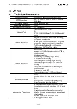
Page 19: ...nsmission distance 100 meters Standard CAT5 CAT5e cable FX Port Parameter Luminous power 12dBm single mode 17dBm multi mode Light absorption sensitivity 38dBm single mode 35dBm multi mode Wavelength 1...

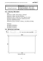
Page 20: ...sation 4 2 Industry Standard EMS EN61000 4 2 ESD 8kV contact 15kV air EN61000 4 3 RS 10V m 80 1000MHz EN61000 4 4 EFT Power Port 4kV Data Port 2kV EN61000 4 5 Surge Power Port 4kV DM 2kV CM Data Port...

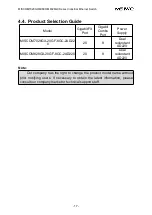
Page 21: ...ort Power Supply MISCOM7028GX 20GF 8GC 2AD22 0 20 8 Dual redundant AD220 MISCOM828GX 20GF 8GC 2AD220 20 8 Dual redundant AD220 Note Our company has the right to change the product model name without p...

Page 22: ...WUHAN MAIWE COMMUNICATION CO LTD Add No 52 Liufang road East Lake Hi tech Development Zone Wuhan China Phone 027 87170215 16 Fax 86 027 87170217 www maiwe com...

Reviews: