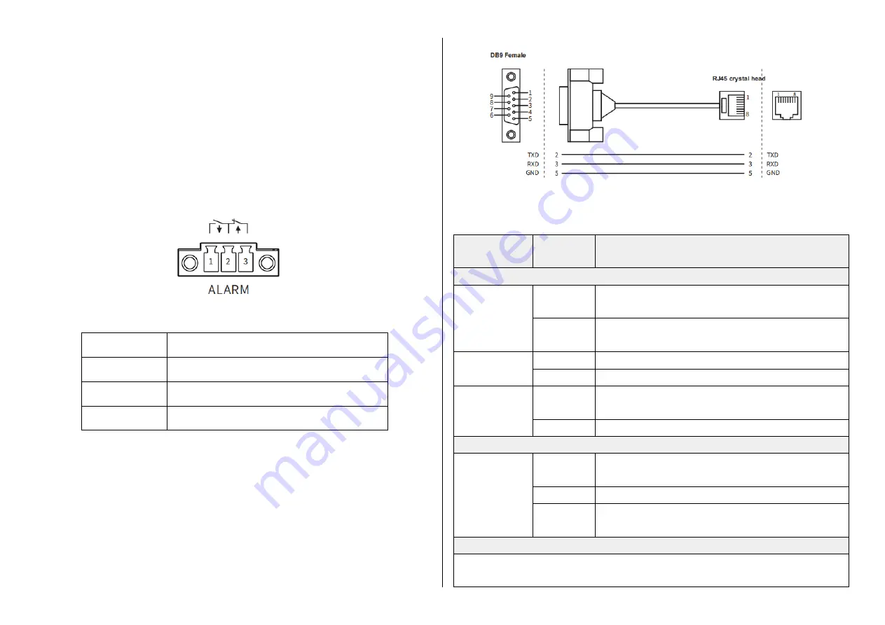
[Connect to the relay]
This series of switches supports the relay alarm function, and the wiring
terminals use 3-position 3.81mm pitch terminals. This relay is a normally open
and a normally closed relay, the middle one is the common terminal, the left
two terminals are normally open relays, and the right two terminals are
normally closed relays. When the switch is working normally, the normally
open relay is powered and closed, and the normally closed relay is
disconnected. The recommended switching load capacity of the relay is 1A
(24VDC).
Number
Pin definition
1
Alarm relay output normally open
2
Alarm relay output common terminal
3
Alarm relay output normally closed
[Connect the CONSOLE port]
The network management port is an RJ45 port, please use the serial port
cable of our company to connect to the serial port of the PC. The interface
communication standard is 3-wire RS232.
The communication parameters of the serial port are as follows:
Baud rate: 115200, data bit: 8, parity bit: None, Stop bit: 1, flow control: None.
The switch indicator lights description is shown in the table below:
Indicator
lights
Status
Definition
System Status LED
PWR1/PWR2
On
The power is connected and operating
normally
Off
The power is not connected or the system is
not operating normally
RUN
Flashing
The system is operating normally
Off
The system is not working properly
ALM
On
Device power failure alarm, port offline alarm,
network storm alarm
Off
Device no alarm
Fiber Port Status LED
GF1-GF4
On
The port has established a valid network
connection
Flashing
There is network activity on the port
Off
No valid network connection is established on
the port
RJ45 Port Status LED
Each RJ45 port has two indicator lights, the yellow light is the port plastic
rate indicator, the green light is the port connection status indicator.


