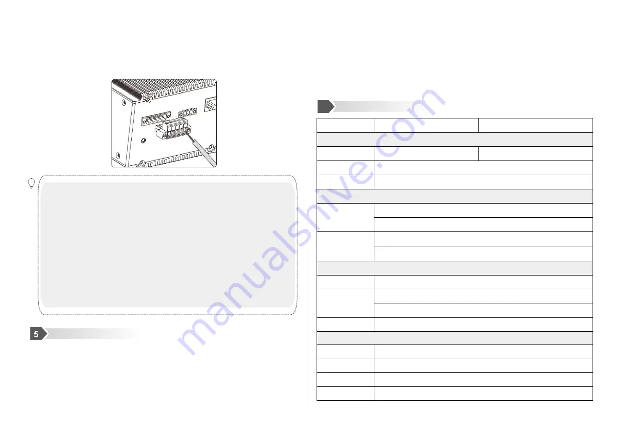
1. When using a switch, the voltage can only be input from V1+ and
V1-, V1+ connects to live wire L, and V1- to neutral wire N. Do not
connect from V2+, V2-; pay attention to safety and prevent electric
shock.
2. Power-on operation: First connect the power cord to the power
terminal of the device according to the definition shown in the figure
above, and then power on.
3. Power-off operation: first unplug the power plug, and then remove
the power cord.
[Power input]
Before connecting the power cord, make sure that the ground is connected.
Do connect the power cord to the power terminal of the device according to
the definition.
The device supports WEB management and configuration. The computer can
access the device through the Ethernet interface, and log in to the main
interface of the WEB server through the browser.
Configure the IP addresses of the computer and the device in the same
network segment and ensure that the computer and device can access
each other.
Enter the IP address of the device in the address bar of the computer
browser, the default IP address is 192.168.16.253.
Enter the user name and password of the device in the login page
Click the "OK" button to log in the WEB interface of the device.
MISCOM7220G-4GF-16GT
MISCOM8220G-4GF16GT
Switch properties
Bandwidth
56G
128G
Cache size
12Mbit
MAC table
16K
Interface
1000M fiber port
4*1000Base-LX
SFP slot
1000M copper port
16*10/100/1000Base-TX RJ45 ports
Full-duplex/half-duplex adaptive, supports MDI/MDI-X adaptive
Power supply
Consumption
15W@24V(MAX)
DC power input
DC24V(18~36V)/DC48V(36~72V)
Supports dual power supply and reverse connection protection
AC power input
AC85~264V (frequency: 47~63Hz) or DC110~370V
Mechanical
Size
156mm×85mm×137.7mm
(
L×W×H
)
(not include din-rail)
Installation
35mm standard din-rail
Heat
Aluminum alloy single-rib chassis surface scattered
IP protection
IP40
Indicator lights
Status
Definition
System Status LED
PWR1/PWR2
On
The power is connected and operating normally
Off
The power is not connected or the system is not operating
normally
RUN
Flashing
The system is operating normally (some models are always
on to indicate normal)
Off
The system is not working properly
Fiber Port Status LED
LINK
On
The port has established a valid network connection
Flashing
There is network activity on the port
Off
No valid network connection is established on the port
RJ45 Port Status LED
Each RJ45 port has two indicator lights, the yellow light is the port plastic rate indicator, the green light is the
port connection status indicator.
10/100M
(Yellow)
On
100M working state (namely 100Base-TX)
Off
10M working status (namely 10Base-T)
Link/Act
(Green)
On
The port has established a valid network connection
Flashing
There is network activity on the port
Off
No valid network connection is established on the port
6
Specifications
Log in WEB Page


