background image

9

Summary of Contents for MJ-9000V

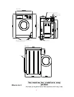
Page 1: ...1 MJ9000V TECHNICAL MANUAL MJ9900 Installation dimension ...

Page 2: ...2 Your machine has a solution to every problem We have put together here a few questions which may come What to do if ...

Page 3: ...arket For your machine to work best we suggest you use non foam detergents that are specifically for automatic washer dryer If you are washing synthetics or woolens you should use detergents made specially for them Above all avoid using dry cleaning solvents such as trichloroethylene or similar products It depends In some areas the water is vary hard and it leaves calcium deposits on both the heat...

Page 4: ...e there is one simple but very important thing you should do Block the drum to save it from bumps To do this put back the blocking screws that were removed when it was installed Maintenance Four simple precaution for this machine Your machine is a washer dryer that has been designed to last without complicated maintenance All the same we would ask you to take care of a few small matters If you fol...

Page 5: ... filter loose the knob in counter clockwise rotation then take out the filter and clean it with water see Fig 3 and Fig 4 Fig 3 Fig 4 Note Re assembly the filter carefully after cleaning ensuring it is fit perfectly and no water can come inside When you do not need a technician Even though your washer dryer has been carefully designed and constructed something could still go a miss with your machi...

Page 6: ...according to instructions given in this booklet When you do not need a technician Check that The plug is fitted firmly into the main socket The door is properly closed The drying time knob is not in position 0 Check that The free end of the drain pipe is not under water The filter is clean do not remove the filter while the washer dryer is running The recommendations for the maximum loads and dryi...

Page 7: ...7 ...

Page 8: ...drying knob 10 Dispenser handle 11 Micro delaying device 12 Porthole catch 13 Porthole catch pin 14 Porthole catch spring 15 Porthole handle 16 Porthole inner frame 17 Porthole glass 18 Porthole frame 19 Support for porthole hinge 20 Porthole hinge 21 Kick plate cover assembly 22 Feet 23 Under panel 24 Vent hose flange 25 Support for capacitor 26 Bracket for capacitor 27 screw 28 Support for speed...

Page 9: ...9 ...

Page 10: ...Spring rest 15 Upper counterweight 16 Retaining ring 17 Bearing 6205 18 Tub spider assembly 19 Bearing 6204 20 Driven pulley 21 Ply V belt 22 Blot Drum pulley fixing 23 Porthole gasket fixing ring 24 Hose connection to porthole 25 Hose connection 26 Porthole gasket and tub fixing ring 27 Bolt M8X45 washer and nut M8 28 Bolt M8X60 washer and nut M8 29 Screw M6X80 nut M6 30 Fix ring for hose of tube...

Page 11: ...11 ...

Page 12: ...19 Bush for motor 20 Motor bolt M6X212 21 Support for drain hose 22 Drain hose 23 Wiring assembly 24 Hopper 25 Pipe for solenoid valve 26 T coupling 27 Inlet water hose 28 Detergent tray 29 Cover for detergent tray 30 Lamp 31 Hopper cover 32 Dispenser spring 33 Transmission for dispenser 34 Ejector guide 35 Ejector 36 37 38 Switches 39 Water feeding valve cool 40 Water feeding valve heat 41 Pressu...

Page 13: ...13 ...

Page 14: ...N 1 Fan motor 2 The wire with fuse 3 Thermostat 2TT NC 125 85 4 Upper body of blower 5 Reflecting screen WDM 6 Heating element 7 Gasket of blower body WDM 8 Lower body of blower 9 Zipper for porthole gasket and blower 10 Fan nut 11 Fan group 12 Clips ...

Page 15: ...15 ...

Page 16: ...16 ...

Page 17: ... attention to color of housing the black housing plug to terminal column with a black point nearby and then yellow to yellow_green to green and so on 7_ Plug the time shaft to cam bush pay attention to the angle and position be sure that the section shape is corresponding with the cam bush hole 8_ Fix time to cabinet using two screw size M5x5 let the wiring at proper position if the hole can not b...

Page 18: ...lt the machine wrest the two front feet two rounds anticlockwise 5_ Tilt the machine forward unscrew tow back feet and then take out under panel 6_ Fetch the V belt from the pulley and Tilt the washing machine forwards 7_ Take off 8P plug housing and ground terminal of the wirings from the motor socket 8_ Use short handle sleeve spanner unscrews right motor bolt size M6x217 and nuts M6 then pull o...

Page 19: ...machine 2_ Move the machine to an open space for repair 3_ Remove back panel by removing three size SD3 5x13mm screws 4_ Remove screw SD3 5x13 take out 2 level pressure switch 20 from cabinet 5_ Pull out all housing of wiring and hose from switch 6_ Replace a new switch connect hose to position move clamp to proper position 2 Level pressure switch 1 level pressure switch ...

Page 20: ...22 terminal of switch Housing No PV23 to 23 terminal of switch 8_ Fix screw SD3 5x13 amount the switch to cabinet 9_ Complete B 1level pressure switch The process is same as above wiring connect as fellow Housing No PV11 to 1 terminal of switch Housing No PV12 to 2 terminal of switch Housing No PV13 to 3 terminal of switch Housing No PV14 to 4 terminal of switch Hose dispenser to tub 9000V 9900 Mi...

Page 21: ...21 2_test C1 80uF C2 80uF 3_connect to wiring Connect C1 C1X terminals of wiring to C1 Connect C2 C2X terminals of wiring to C2 Speed regulator 1_picture C1 C2 ...

Page 22: ...r from regulator support 6 _replace a new speed regulator 7_connect wiring to speed regulator as fellow Plug terminal RV1 of wiring to 1 terminal of regulator Plug terminal RV2 of wiring to 2 terminal of regulator Plug terminal RVF of wiring to F terminal of regulator 24 Plug terminal RV3 of wiring to 3 terminal of regulator Plug terminal RV4 of wiring to 4 terminal of regulator Plug terminal RV5 ...

Page 23: ...ontrol panel 4_unscrew two screw size M4x6 from control panel 5_take out drying timer from control panel 6_pull out all terminals of wiring 7_change a new timer and connect terminals as fellow Plug terminal No TAA of wiring to a terminal of timer Plug terminal No TAA1 of wiring to a1 terminal of timer Plug terminal No TAB of wiring to b terminal of timer Plug terminal No TAB1 of wiring to b1 termi...

Page 24: ...24 Fan motor Connection Plug terminal MV of wiring to upper terminal of fan motor Plug terminal TF of wiring to lower terminal of fan motor Pump 1_picture 2_connection to wiring ...

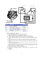
Page 25: ...25 Fan Heat element ...

Page 26: ...g to upper terminal of fan motor 2 plug TF terminal of wiring to lower terminal of fan motor 3 plug FEX and FE terminals of wiring to terminals with red point of thermostats 4 plug FDX and FD terminals of wiring to terminals with black point of thermostats 5 plug RA terminal to a terminal of heater ...

Page 27: ...27 ...

Reviews: