24
GBR Series B-Vent Gas Fireplace
7412955
Accessories
Glass Doors
B-fold and single panel glass doors are available to
enhance the viewing of the fireplace.
Models
36GSKBB
36GDKBB
36GDKBK
36GDKDP
36GDKS
Outside Air Kit
The Model AK-MST Outside Air Kit is designed to bring
additional combustion air directly from the outside to the
fireplace. Refer to installation instructions provided with
the Outside Air Kit.
Thermal Vent Damper
Installing the TVD4 Thermal Vent Damper reduces cold
air infiltration when fireplace is not in use by opening
and closing automatically.
Attach the thermal vent damper to the combustion
dome with 2 screws. Be sure the tab points down. (Fig.
23)
Start the appliance and operate it for approximately 5
minutes. Turn the unit off and check if the vent damper
is in the open position (blades down from the horizontal
position). If the damper has not opened, check installa-
tion.
NOTE: Not for use in Canada.
Remote Controls
Optional remote control units are available to control
different functions of the appliance.
Model
Function/s Controlled
MRC1
“ON/OFF”
MRC2
“ON/OFF” and Temperature
MRC3
“ON/OFF” and Temperature control
with a digital and a programmable 24
hour clock
Ceramic Refractory Panels
The GBRCR ceramic refractory panels enhance the
appearance of the appliance and give a realistic brick
look.
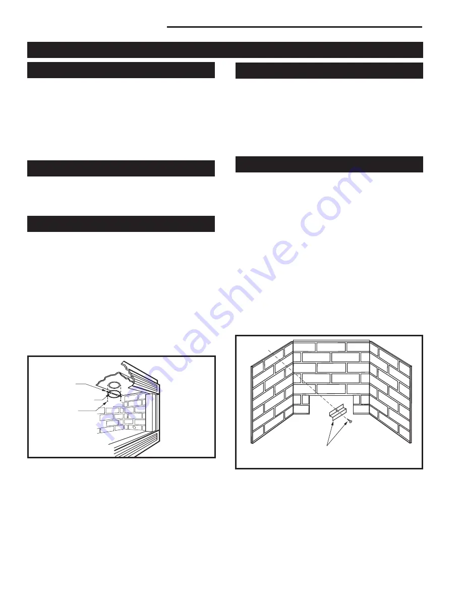
1. Remove glass doors and log set.
2. Install back panel over and behind the burner (cut
out area facing down). Center the panel and install a
side panel.
3. Install side panels and butt against the back panel.
Be sure to align the grout lines to match back panel.
4. Use bracket as a template, place bracket against
ceramic panel as shown in Figure 24. Bottom lip of
bracket should hold panel in place. Drill one 1/8"
diameter hole in combustion casing and secure back
panel in place with one sheet metal screw and one
bracket. Repeat procedures for other two panels.
FP844
GBRCR Ceram Pan Inst
02/23/99
(1) Bracket and
(1) Screw per Panel
FP844
Fig. 24
Panel installation.
FP577
NVB—TVD6/7
11/17/97
FP577
Fig. 23
Attach the thermal vent damper.
Tab
Thermal Vent Damper
Screws


