background image

16

BFC36 Balance Flue Heat-Circulating Fireplace

7412647

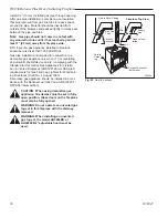
WARNING:  Hearth extension must be installed in 
accordance with Figure 23 and must not cover the 
bottom front opening of the circulating model.

Alternate noncombustible materials may be used pro-
viding the (total) thermal resistance (Rt value) of the al-
ternate material employed is greater than or equal to R 
=  1.09 Thermal resistance (R) or thermal conductivity 
(K), may be obtained from manufacturer of the material.  
Factors are related by the formula K = 1/R. (Fig. 24)
T = given thickness
R = thermal resistance for a given thickness (T)
K = thermal conductivity
Noncombustible material with a lower R value may 
be used, provided thickness of material is sufficiently 
greater to maintain an equivalent (total) thermal resis-
tance (Rt).

COMMON MATERIALS AND FACTORS

MATERIAL

K*

R

MINIMUM

THICKNESS

EH2416 

Common Brick

0.458

5.0

1.09    0.50 in.**        

0.10    5.46 in.**       

(CFM Corporation)

   R Value is for 1/2 inch.

 * Units of K = BTU/SQ FT/HR/˚F/IN

** Thickness of Listed Material

FP533ADD

Addendum

6/1/99   djt

8/4/99 changed .2 to .1

one inch to 1/2 inch  djt

FP533ADD

Fig. 22 

 Hearth extension material factors.

Example of Determining Hearth Extension 
Equivalents

To determine the thickness required for any 

new

 mate-

rial:

NEW 

  K of new material (per inch) 


thickness

required 

=  ---------------------------------------  X  of listed

thickness 

  K of listed material (per inch)   

material

Example for Common Brick

T (new) = 5.0/0.458 x 0.50 in. = 

5.46 in.

 (new required 

thickness).

FP550

BR/BC - SEALING

DETAILS

9/29/97

Wall Covering

Noncombustible 

Decorative Fac-

ing

Seal all cracks 

between fireplace 

surround and wall 

materials with non-

combustible material.

Noncombus-

tible Decorative 

Covering

Hearth Exten-

sion Insulation

2 x 4” Header 

- Do not notch at 

standoffs

Seal crack between 

fireplace and hearth 

extension with noncom-

bustible material

Safety Strips - 

Must be overlapped 1/2” 

minimum

Side View

FP550

Fig. 23

  Sealing gaps.

Install Door Handles

1.  Remove the door handle stubs from the plastic bag. 
2.  Remove the large locking nut from right door handle 

stub shaft. (Fig. 24) 

FP1595

Door Pawl parts

11/05

Pawl

Handle 
Shaft

Washer

Large 

Locking 

Nut

Spacer

Handle 

Stub

FP1595

Fig. 24

  Right door handle stub parts.

Set 

Screw

3.  Using 1/8” Allen wrench loosen the set screw and 

remove the pawl, spacer and washer.

4.  Insert handle shaft through handle opening in right 

door. 

5.  With the handle pointing down and the flat side of 

the threaded shaft facing up, replace the washer, 
spacer and pawl. Be sure the door adjustment por-
tion of the pawl is on the left side of the handle stub. 
Secure with large locking nut. Tighten set screw 

Summary of Contents for Monarch BFC36

Page 1: ...Closed Combustion Heat Circulating Fireplace Model BFC36 For use in the U S Canada Underwriter s Laboratories Report No MH6018 DO NOT DISCARD THIS MANUAL Retain for future use 7412647 4 07 Rev 13 Hom...

Page 2: ...d or approved by CFM Corpo ration in combination or assembly with a CFM Corporation replace system notwithstand ing any independent testing laboratory or other third party approval of such component p...

Page 3: ...ge 647 BFC36 specs 8 18 00 djt 13 Dia 343mm Rough Opening Width 43 Rough Opening Height Rough Opening Depth Gas Line Access 51 1297mm 51 1297mm 1 8 3 4 m m 197mm 23 584mm 610mm 624mm 39 997mm 246mm 35...

Page 4: ...tstop Standoff Surround Trim Ledge Standoff Glass Door Romex Pigtail Gas Line Access Knock out Each Side Air Inlet Basket Grate Bottom Grille Metal Safety Strip s Shown not inplace 1 2 or 3 pieces Nai...

Page 5: ...et of angled run of chimney Chimney supports are required for every 30 feet and 60 feet of vertical chimney height above the hearth Determine the offset distance of your chimney arrangement from the c...

Page 6: ...2 total 45 elbows in Canada per replace may be used 6 A guy wire stabilizer is required for chimneys extend ing more than 6 1 8m above a roof line The Ten Foot Rule Major U S building codes specify a...

Page 7: ...w the chimney system should be run contact your Ver mont Castings Majestic Products dealer for assistance Installation Insulating Fireplace Enclosure for Cold Climates If you live in a cold climate it...

Page 8: ...ts must be tight NOTE Check local building codes to determine if junction box is required at the romex pigtail house wire connection Also check junction box and speed control SCVS installation instruc...

Page 9: ...ut Check to see where existing ceiling joists and other possible obstructions are located i e wiring plumbing etc If necessary re position chimney and or replace to avoid obstructions Cutting the Hole...

Page 10: ...in front of the replace This Z shaped safety strip is not provided but must be fabricated of metal with each horizontal leg at least 1 38mm wide and equal in length to the metals strips provided with...

Page 11: ...ness up to 8 203mm When combined thickness of ceiling material ceiling joists and ooring material exceeds 8 203mm adjustments must be made in framing to assure that minimum air spaces to chimney are m...

Page 12: ...y adjacent combustible surfaces Combustible surfaces include burnable materials such as ceiling members joists ooring combustible insulation and roof structures WARNING Do not pack required air spaces...

Page 13: ...ns are not a substitute for local building codes You must check your local building codes to determine speci c requirements for your city or state NOTE Other building materials may be required in addi...

Page 14: ...antel clearances 12 from top of grille opening 6 from top of grille opening Face Plate FP531b mantel clearances 9 03 djt 12 305mm Max 12 305mm Min 1 38mm 6 159mm Min Fig 19 Mantel clearance Combustibl...

Page 15: ...protect hearth extension material Fig 21 Secure the hearth extension to the oor to prevent shifting using trim molding or other similar means at three 3 outer edges Seal crack between the replace hear...

Page 16: ...mine the thickness required for any new mate rial NEW K of new material per inch thickness required X of listed thickness K of listed material per inch material Example for Common Brick T new 5 0 0 45...

Page 17: ...tub to the right and up Close the door and turn the handle stub to the left and down to secure door Fig 26 Left Handle is Stationary Turn Counter clockwise to Open FP1596 Fig 26 Turn right door handle...

Page 18: ...d 2 complying with the Standard for Decorative Gas Appliances for Installa tion in Vented Fireplaces ANSI Z21 60 or CSA draft requirements for Gas Fired Log Lighters for Woodburn ing Fireplaces Draft...

Page 19: ...20008275 5 Right Door Assembly Complete 20008276 6 Rear Firebrick 2353145 7 Side Firebrick two per replace 2353146 8 Hearth Firebrick 2353140 9 Nailing Flange four per replace 2422198 10 Fiberglas Rop...

Page 20: ...Balance Flue Heat Circulating Fireplace 7412647 BFC Balanced Flue Fireplace continued 25 Stud 3 8 16 x 1 20009776 26 Nut Hex Jam 3 8 16 Toplk 1203290 27 Black Fall Away Handle 20006382 Ref Descriptio...

Page 21: ...such must be oper ated only with CFM Corporation approved components If you use an unapproved component to make any modi cations you may create a possible re hazard and will void the CFM Corporation...

Page 22: ...ng is not included TT200C Adapter Kit TT8CB is required Chase Top Housing Used with chase terminations to prevent rain entry FL88 8 ue Contemporary Flashing 8 6 12 with 8 ue Required for Contemporary...

Page 23: ...place installed in the continental United States the state of Alaska and Canada only if and so long as the Fireplace is installed or serviced by a quali ed installer preferably NFI or WETT Canada cert...

Page 24: ...410 Admiral Blvd Mississauga Ontario Canada L5T 2N6 800 668 5323 www cfmcorp com CFM Corporation...

Reviews: