


5
Majestic
®
Fireplaces Power Venting System
51810
FP1417
powervent
system
front view
11/24/03 djt
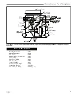
4” (102 mm) Insu-
lated Flue Liner
Sound Reducer
Sheet Metal
Screws
Fireplace Top
Fireplace
FP1417
Fig. 1
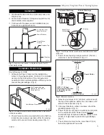
Secure sound reducer to fireplace top with four (4)
sheet metal screws.
Installation Restrictions
Sound Reducer Kit SR6
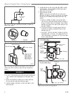
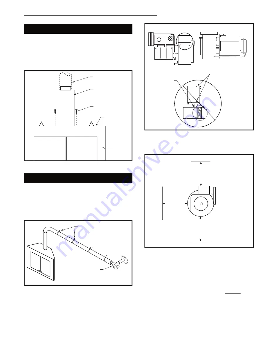
1. Although the Power Venter can be installed any-
where in the exhaust system, it is best if it is installed
as close to the termination of the vent system as
possible to obtain optimal appliance efficiency and to
prevent flue gas leakage. (Fig. 2)
FP1418
power vent location
11/24/03 djt
Vent Support Hangers
Spaced 36” (914mm) on
Horizontal Run
Anti-Vibration Sleeve
FP1418
Fig. 2
It is best to install Power Venter as close to the termi-
nation as possible.
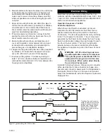
2. Power Venter must be mounted with motor shaft hor-
izontal to ensure proper operation of the fan proving
switch and to prevent motor bearing wear. (Fig. 3)
FP1419
motor views
11/25/03 djt
Horizontal Discharge
Vertical Discharge
Oil Holes
Motor Shaft
Vertical
Incorrect
FP1419
Fig. 3
The Power Venter must be mounted with motor shaft
horizontal.
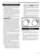
3. Power Venter housing in single wall a 6” (152 mm)
clearance must be maintained. (Fig. 4)
6" (152mm)
Minimum
6" (152mm) Minimum
6" (152mm) Minimum
FP1420
Minimum clearance
11/25/03 djt
Combustible Material
Combustible Material
Combustible Material
Power Venter
NOTE: 6” (152mm)
maximum clearance from
combustible must be
maintained.
FP1420
Fig. 4
Minimum clearance.
4. Allow for a minimum of 18” (457mm) vertical rise off
the top of the appliance before the vent makes a 90°
elbow to the horizontal. (Fig. 5)
5. Vent pipe transitions, where necessary, should be
gradually tapered. (Fig. 6)
6. Power Venter to vent pipe connections and all joints
on the outlet side of the Power Venter must be
sealed with high temperature silicone sealant or alu-
minum vent pipe tape to prevent flue gas leakage.
(Fig. 7)
7. The vent terminal must not be more than 20’ (6m)
below the appliance’s flue outlet.
Installation
1. Slip Sound Reducer into flue collar and press on to
fireplace top.
2. Fasten Sound Reducer to fireplace top with four (4)
sheet metal screws supplied.
3. Continue with the power venter installation as per
instructions supplied with same.


