8
Majestic
®
Fireplaces Power Venting System
51810
Operation and Checking the Draft
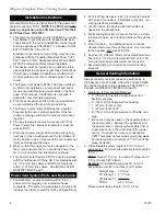
1. Insofar as is practical, close all doors, windows and
air inlets to the building. Turn on all exhaust fans
(range hood, bathroom exhaust, etc.) so they will
operate at maximum speed.
2. Place appliance into operation. See fireplace
manual for gas start up information. Once pilot has
been lit and gas valve has been set open, activate
power switch, or where applicable, adjust thermostat
so the appliance will operate continuously. At this
point the fan will start up and once air flow has been
proven the main burner will start.
3. After allowing appliance to operate for five (5) min-
utes, test for spillage at the draft hood relief opening
or at fireplace front opening.
Checking the Draft.
Allow the vent connected gas
utilization equipment to operate for several minutes.
Then check to see that the combustion products
are going up the chimney or gas vent properly, by
passing a lighted match or taper around the edge
of the relief opening of the draft hood. If the chim-
ney or gas vent is drawing properly, the smoke
from the match flame will be drawn into the draft
hood or opening. If smoke is not drawn in, then the
combustion products are escaping from the relief
opening into the room. Under these conditions, the
equipment must not be operated until proper adjust-
ments or repairs are made to provide adequate draft
through the chimney or gas vent.
4. Next, turn on all other fuel-burning appliances within
the same room so they will operate at their full input.
Repeat Step C above, checking the draft on each
appliance.
5. The Air-Flow Adjustment on the Power Venter is fac-
tory set for maximum air flow. Operating a properly
sized Power Venter at maximum setting will assure
that combustion gases are safely removed to the
outside. If the Power Venter has excess venting
capacity than what is required for this application,
operating the Power Venter with the Air-Flow Adjust-
ment at the maximum setting may draw more dilu-
tion air than necessary.
The Air-Flow Adjustment may be set by use of a
combustion analyzer, inclined manometer or draft
gauge. Alternatively, the Air-Flow adjustment can be
set using a smoke candle or taper, as follows:
a. With exhaust fans operating, air inlets closed and
all appliances firing (as instructed above), hold
lighted match or taper around the edge of the re-
lief opening of the draft hood or fireplace opening.
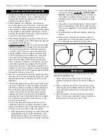
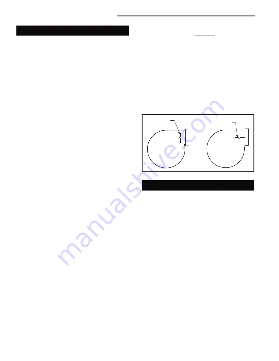
b. Set Air-Flow Adjustment by loosening locknut and
turning rod handle.
CAUTION: HANDLE MAY
BE HOT
, use pliers to move handle. Position of
rod handle on outside of Power Venter housing
indicates position of Air-Flow Adjustment inside
housing.
c. Using pliers, move handle towards minimum draft
setting until spillage is detected at relief opening,
then re-open Adjustment just enough to eliminate
spillage.
d. Lock Adjustment at desired setting by tightening
locknut.
e. Return doors, windows exhaust fans and fire-
place dampers to their previous condition of use.
f. Turn off appliances started in Step 4 above.
FP1427
damper
11/25/03 djt
Damper Closed
Damper Open
FP1427
Fig. 10
Adjustable damper control.
Maintenance
The Power Venters must be inspected semi-annually.
Points of inspection are:
1. Motor - Motor must rotate freely. Oil every six
months of operation with four (4) drops of SAE 20
oil.
2. Wheel - Wheel must be clean of soot, ash or any
other coating which inhibits rotation or air flow. Re-
move all foreign material from vent system before
operation.
3. Pressure Switch - Pressure Switch must operate
freely. Verify proper operation by observing Opera-
tion Sequence at least every six months.

