background image

53D0419

DV6000 Gas Fireplace

9

note 

: The gas line connection may be made using 

1

/

" rigid tubing or an approved flex connector. Since some 

municipalities have additional local codes it is always best to consult your local authorities and the current edition 
of the National Fuel Gas Code ANSI.Z3.1, NFPA54. In Canada CSA-B149 (1 or ) Installation Code. 
A listed manual shutoff valve must be installed upstream of the appliance. Union tee and plugged 

1

/

8

" NPT pres-

sure tapping point should be installed upstream of the appliance. 

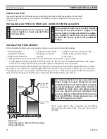
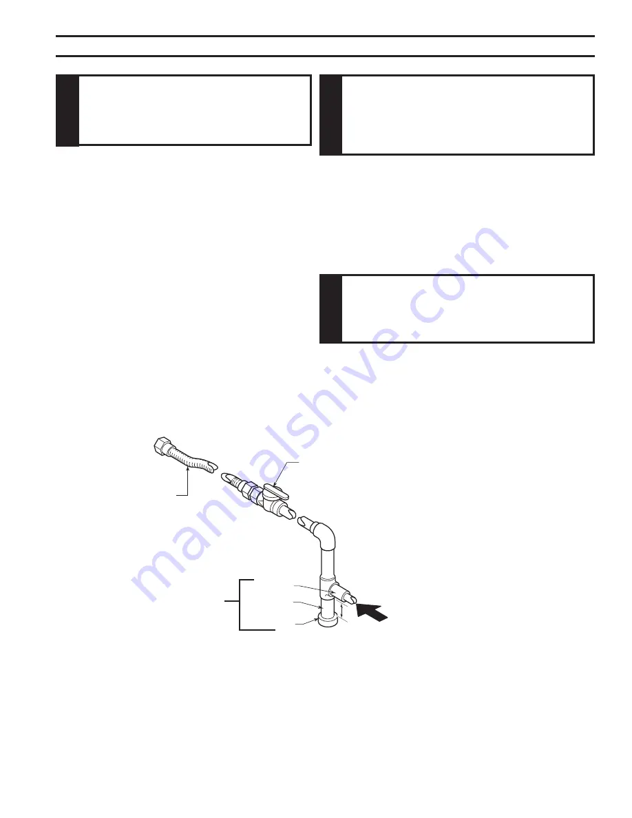
Figure 35

IMportant:

 Install main gas valve (equipment shutoff valve) in an accessible location. The main gas valve is 

for turning on or shutting off the gas to the fireplace.


Check your building codes for any special requirements 
for locating equipment shutoff valve to fireplaces.
Apply pipe joint sealant lightly to male threads. This will 
prevent excess sealant from going into pipe. Excess seal-
ant in pipe could result in clogged burner system valves.
We recommend that you install a sediment trap/drip leg 
in supply line as shown in 

Figure 35

. Locate sediment trap/drip leg where it is within reach for cleaning. Install 

in piping system between fuel supply and burner system. Locate sediment trap/drip leg where trapped matter 
is not likely to freeze. A sediment trap traps moisture and contaminants. This keeps them from going into the 
burner system gas controls. If sediment trap/drip leg is not installed or is installed wrong, burner system may 
not run properly. 

natural Gas

From Gas Meter 

(4.5" w.c. to 10.5" w.c. Pressure)

propane/lp

From External Regulator 

(11" w.c. to 13" w.c. Pressure)

3" Minimum

FP1978
gas connection

FIreplace InstallatIon 

Figure 35 - 
Gas Connection 

Approved Flexible Gas Line 

CSA Design-Certified Equipment 
Shutoff Valve with 1/8" NPT Tap*

w

arn

In

G

only  persons  licensed  to  work  with  gas 
piping  may  make  the  necessary  gas 
connections to this appliance.

caut

Ion

a  manual  shutoff  valve  must  be  installed 
upstream  of  the  appliance.  union  tee  and 
plugged  1/8”  npt  pressure  tapping  point 
should be installed upstream of the appliance. 

Figure 35

caut

Ion

use pipe joint sealant that is resistant to liquid 
petroleum (lp) gas.

Pipe Nipple

Cap

Tee Joint

Sediment Trap/Drip Leg 

Summary of Contents for DV6000

Page 1: ...onsult a qualified installer service agency or the gas supplier This appliance may be installed in an aftermarket permanently located manufactured home USA only or mobile home where not prohibited by...

Page 2: ...ermination Configuration 22 Below Grade Installation 24 Vertical Through the Roof Installation 25 Installation for Vertical Termination 26 Flat Ceiling Installation 26 Fireplace Installation 28 Check...

Page 3: ...properly installed by a qualified service person The glass door must be properly seated and sealed If this unit is not properly installed by a qualified service person with glass door properly seated...

Page 4: ...r Immediately call a qualified service person to arrange for replacement of the unit 19 Do not operate fireplace if any log is broken 20 Do not use a blower insert heat exchanger insert or any other a...

Page 5: ...determined under continuous operating conditions and was determined indepen dently of any installed system Code Approval Direct Vent type appliances draw all combustion air from outside of the dwelli...

Page 6: ...tems Required For Installation Tools Building Supplies Phillips Screwdriver Framing Materials Hammer Wall Finishing Materials Saw and or saber saw Caulking Material Noncombustible Level Fireplace Surr...

Page 7: ...0200 6000Dv penin dims FIREPLACE DIMENSIONS Gas Electric Access See Through and Peninsula Model Dimen sions 3256M 356M 18 6 4 6QE 39 6 2456O 1 6M 1956O 37 6M 405 6QE 5 8 1 2 44 37 6M 5 8 1 2 420200 60...

Page 8: ...particle board or other hard surfaces Be sure firebox rests on a solid continuous floor or platform with appropriate framing for support No cold air should enter room from under the firebox FIREPLACE...

Page 9: ...d flue pipe adaptor Refer to Page 16 Figures 10 and 11 Reattach both assemblies C A 2 B A 1 A1 A2 C FP2038 designer see thru framing 10 08 See through Framing Top View 2 x 4 Minimum Gas Connection 2 x...

Page 10: ...system chimney of this fireplace should be checked at least once a year and if needed your venting system should be cleaned 8 Keep the area around your fireplace clear of combus tible materials gasoli...

Page 11: ...etween the edge of a glass panel and an adjacent wall 3 B Island Location X Maximum length of horizontal venting 20 Refer to the venting section of this manual for specific dimensions pRE INSTALLATION...

Page 12: ...o 2 wood screws or masonry concrete screws to secure fireplace to the floor Use four 4 screws to attach fireplace to framing The side brackets are adjustable from 1 2 to 5 8 to accommodate different t...

Page 13: ...liance Figure 8 Mantel Clearances 2 4 6 8 10 4 6 8 10 12 FP2279 mantel clearance 2 09 Wall Insulation Board Standoff Top of Louvers FP2279 WARNING Never obstruct or modify the air inlet or outlet gril...

Page 14: ...adders or when on rooftops Be aware of electrical wiring locations in walls and ceilings The following actions will void the warranty on your venting system Installation of any damaged venting compone...

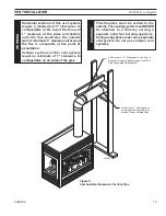
Page 15: ...g system must NEVER be attached to a chimney serving a separate solid fuel burning appliance Each gas appliance must use a separate vent system Do not use common vent systems WARNING Horizontal sectio...

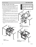
Page 16: ...10 4 Remove eight 8 screws securing the flue pipe to the back of the intake box and remove the pipe and gasket Figure 11 5 Replace flue pipe to top of firebox Ensure the gasket is in place and undamag...

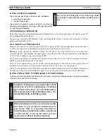
Page 17: ...are required at each floor level If an offset is needed in the attic additional pipe and elbows will be required You may use a chase with a vent termination with exposed pipe on the exterior of the h...

Page 18: ...ir supply inlet to building or the combustion air inlet to any other appliance 12 305 mm minimum K Clearance to a mechanical air supply inlet 6 1829 mm minimum L Clearance above a paved sidewalk or pa...

Page 19: ...ple If the vertical dimension from the floor of the unit is 7 2 14m the horizontal run to the face of the outer wall must not exceed 8Z x 2 6 m Sidewall Vent Graph showing the relationship between ver...

Page 20: ...e male end of adjacent pipes and fittings Push the pipe sections together and twist one section clockwise approximately one quarter turn until the sections are fully locked Figure 17 3 Attach vent pip...

Page 21: ...ded to attach the standoff Figure 19 5 Slide fire stop over the vent pipe before connecting hori zontal run to vent cap Figure 20 6 Insert vent pipe into the horizontal termination The pipe overlap sh...

Page 22: ...in such a way that minimizes the number of offsets and horizontal vent length The horizontal vent run refers to the total length of vent pipe from the flue collar of the fireplace or the top of he Tr...

Page 23: ...ermitted per side wall installation is two 2 These elbows can be installed in either the vertical or horizontal run For each 45 elbow installed in the horizontal run the length of the horizontal run M...

Page 24: ...a depth of approximately 16 below base of snorkel Install drain pipe Install window well not supplied Refill hole with 12 of coarse gravel leaving a clearance of approxi mately 4 below snorkel Figure...

Page 25: ...ontal length No elbows 10 3 m 1 x 45 elbows 8 5 2 6 m 2 x 45 elbows 7 2 1 m A minimum of an 8 2 5 m vertical rise is required Two sets of 45 elbows offsets may be used within the vertical sections Fro...

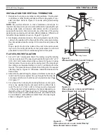
Page 26: ...ting hole as a center point The opening should be framed to 9Z x x 9Z x 241 x 241 mm inside dimensions as shown in Figure 32 using framing lumber the same size as the ceiling joist If the area above t...

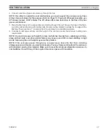
Page 27: ...p edge of the flashing There must be a 1 clearance from the vent pipe to combustible materials 6 Continue to add pipe sections until the height of the vent cap meets the minimum building code requirem...

Page 28: ...pressure to between 11 and 13 inches of water If you do not reduce incoming gas pressure burner system regulator damage could occur Install external regulator with the vent pointing down as shown in...

Page 29: ...install a sediment trap drip leg in supply line as shown in Figure 35 Locate sediment trap drip leg where it is within reach for cleaning Install in piping system between fuel supply and burner syste...

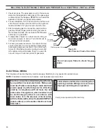
Page 30: ...to reseal Do not over torque Check test points for gas leaks Electrical Wiring This fireplace will work without any electrical supply Electricity is only needed to operate blower NOTE If installed in...

Page 31: ...ch wire length provided NOTE Extended lengths of wire may cause the fireplace not to function properly Longer length of wire is permitted if the wire is made out of larger gauge diameter wire Always c...

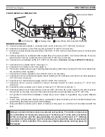
Page 32: ...This replaces the 15 wall switch connection to the switch Figure 38 3 Mount remote control receiver at junction box for your wall switch WARNING Do not connect 110 120V AC to the Remote Wall Switch T...

Page 33: ...of fireplace Figure 39 2 Tilt glass frame out and lift glass frame up until it clears three tabs on top of fireplace 3 Set glass frame aside Figure 39 Removing Glass Frame Glass Frame Three Tabs Clamp...

Page 34: ...to prevent skin irritation from ceramic fibers After handling the logs wash your hands gently with soap and water to remove any traces of fibers LG639 Figure 41 Install Right Log 2 Right Log 2 Pins Co...

Page 35: ...ug right end of bottom center back log 3 to the middle of right log 2 Figure 42 6 Line up pin holes on bottom front log 4 with pins on grate Figure 43 LG641 bottom front log Bottom Front Log 4 Pins LG...

Page 36: ...tion other end of top log 6 in cutout of bottom center log 3 Figure 45 Rock Wool L643 DV6000 top log Figure 45 Install Top Log 6 Top Log 6 Cutout on Bottom Center Log Grate Prong Four Control Panel 9...

Page 37: ...back the screw all the way out 3 Slide the baffle on top of the restrictor plate to block a percentage of the grille opening Refer to the chart below for recommended settings Note All the settings abo...

Page 38: ...nician Force or attempted repair may result in a fire or explosion D Do not use this appliance if any part of it has been under water Immediately call a qualified service technician to inspect the app...

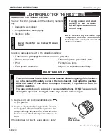
Page 39: ...when the magnet is closed it is possible to start the lighting operation The gas control knob is designed to be operated by hand DO NOT use any tools during this operation Damaged knobs may result in...

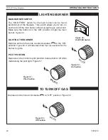
Page 40: ...tch allows you to turn on and to turn off the main burner without using the gas valve knob Make sure the button is in the ON position to light the main burner Figure 49 Lighting the burner Depress and...

Page 41: ...They will damage the glass surface pilot and burner flames firebox cleaning 1 Carefully remove log set and embers rock wool from combustion chamber 2 Vacuum burner compartment thoroughly 3 Vacuum or...

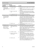
Page 42: ...mocouple connec tion at the gas valve is fully inserted and tight Disconnect the thermocouple from the valve place one millivolt lead wire on the tip of the thermocouple and the other meter lead wire...

Page 43: ...blocked B Check electrical connections between module and pilot operator on gas control C Check for 24VAC across PV MVPV terminals If voltage is correct replace gas control If voltage is not correct...

Page 44: ...and air intake area Make sure this area does not have any blockage from debris and clean Check gas supply A Ensure that the vent cap is installed properly and free of debris Ensure that the vent syste...

Page 45: ...approved with this appliance may result in property damage or personal injury Ref Description Qty Natural Propane 1 Left Bottom Log 1 1 42D0401 42D0401 2 Right Bottom Log 2 1 42D0400 42D0400 3 Bottom...

Page 46: ...Propane 1 Junction Box 1 26D2128K 26D2128K 2 Large Glass Assy 1 42D0364K 42D0366K Peninsula See through 2 Large Glass Assy 1 42D0366K 42D0366K Corner Left Corner Right 3 Small Glass Assy 1 42D0365K 42...

Page 47: ...8 41D0048 5 Piezo Igniter 1 14D0503 14D0503 6 Injector 1 37D0362 37D0349 7 Burner Assy 1 42D0351 42D0351 8 Wire Assy Female 1 44D0500 44D0500 8 Wire Assy Male 1 44D0501 44D0501 Accessories 9 Thermosta...

Page 48: ...Pilot Assy 1 37D0020 37D0021 3 Flexhose w Shut off Valve 1 69D0030 69D0030 4 Rocker Switch 1 41D0048 41D0048 5 Injector 1 37D0362 37D0349 6 Burner Assy 1 42D0351 42D0351 7 Wire Assy 1 54D2001 54D2001...

Page 49: ...bow and BHSTK 11 x 14B Adjustable Pipe 1 1 Horizontal Flexible Pipe Termination Kit w Horizontal Termination Cap w BHSFTK Built in Vinyl Siding Standoff Heat Deflector Firestop 20 to 40 Flexible Pipe...

Page 50: ...d carbon monox ide detector with an alarm is installed on each additional level of the dwelling building or structure served by the side wall horizontal vented gas fueled equipment It shall be the res...

Page 51: ...ted gas fueled equipment does not provide the parts for venting the flue gases but identifies special venting systems the following requirements shall be satisfied by the manufacturer 1 The identifica...

Page 52: ...52 53D0419 DV6000 Gas Fireplace...

Page 53: ...53D0419 DV6000 Gas Fireplace 53...

Page 54: ...54 53D0419 DV6000 Gas Fireplace...

Page 55: ...me Warranty will also be void if the appliance is not operated and maintained according to the operating instructions supplied with the appliance and does not extend to 1 firebox burner assembly damag...

Page 56: ...MARCH 2009 53D0419 Rev 10 MHSC 149 Cleveland Drive Paris Kentucky 40361 www mhsc com Efficiency Ratings Model EnerGuide Ratings Fireplace Efficiency DV6000NV DV6000PN DV6000NE DV6000PE...

Reviews: