background image

Part 3: 

Operating Instructions 


Log Installation 
 

Warning: As with all plastic bags, these bags are not toys and should 

always be kept away from children and infants. 


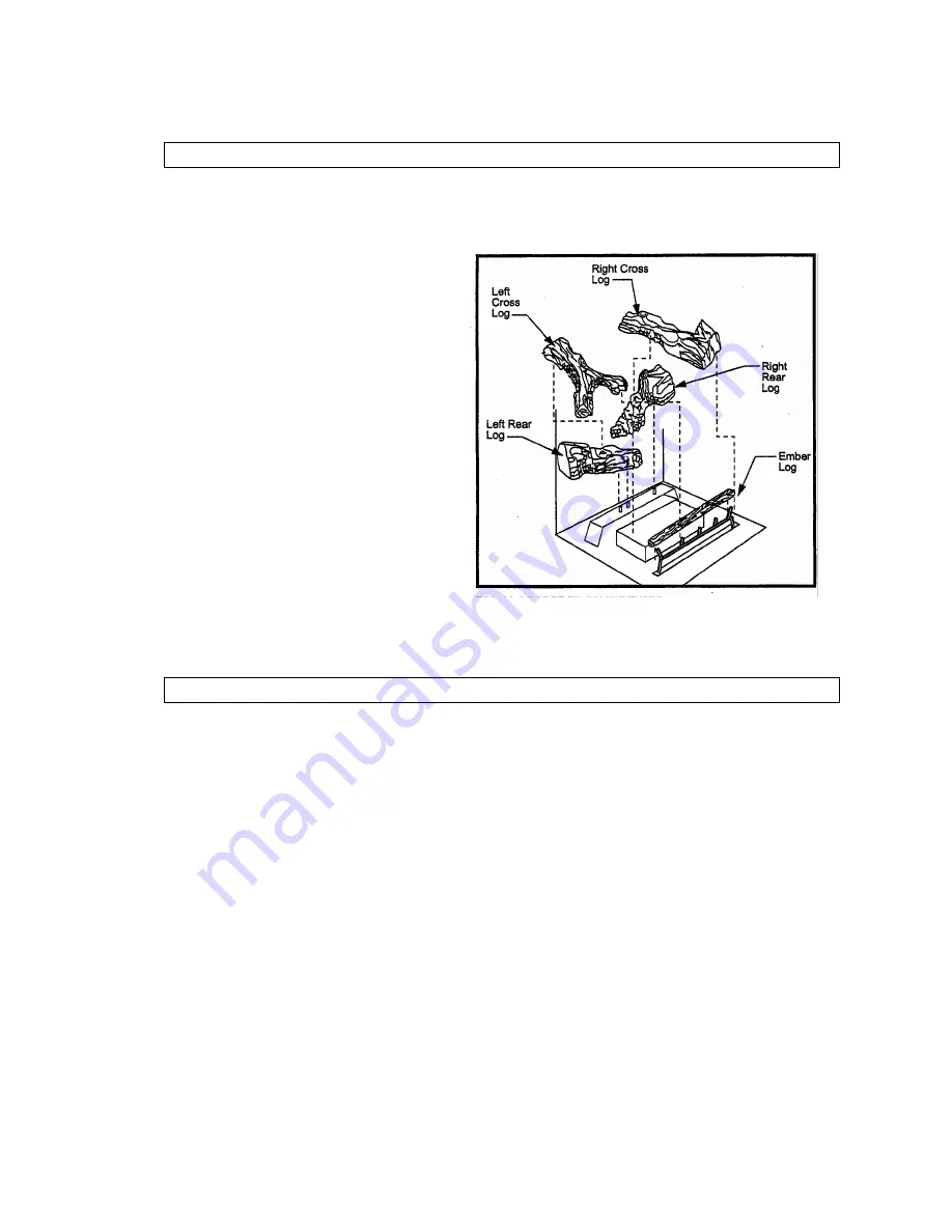
1. Remove logs from packaging. 
 

2.  Place left rear log on rear 

support. Ensure that log is firmly 

positioned and there is no side 

to side movement. (Refer to 
Figure 11) 

 
3.


Carefully place ember log 

between grate and burner.  

 
4.


Place the front of right rear log 

on the burner and the back of 
the log on the rear log support. 


5.


Place the top logs onto the 

locator notches. Ensure the logs 

are secure. 


Figure 11 

 
First Firing 
 

Upon completion of the gas fitting line, a small amount of air will be trapped in the 
gas pipe. When first lighting the pilot light, it will take a few minutes to purge the 

trapped air.  
 

Once purging is complete, the pilot and burner will light and will operate as outlined 

in the instruction manual. Subsequent lighting of the appliance will not require 
purging. 

 
When lit for the first time, the appliance will emit a slight odour for an hour or two. 

This is due to the paint and lubricants used in the manufacturing process.  


Page 11 of 18 

Summary of Contents for ODGSR36ANAU

Page 1: ...MAJESTIC OUTDOOR GAS FIREPLACE Model ODGSR36ANAU ODGSR36APAU Installation and Operating Instructions Page 1 of 18 ...

Page 2: ...nd Finishing Final Finishing Gas Specifications Gas Inlet and Burner Pressures High Elevations Valve Access Gas Fitting Line Installation Part 3 Operating Instructions Log Installation Lava Rock First Firing Flame Adjustment Flame Characteristics Lighting and Operating Instructions Troubleshooting Part 4 Maintenance Part 5 Replacement Parts Part 6 Warranty Page 2 of 18 ...

Page 3: ...s supply at meter Immediately call Rheem Service or your gas supplier or licensed gas fitter Note Some gases are heavier than air and it maybe necessary to check for gas leaks at floor level CAUTION DO NOT operate this appliance before reading this instruction booklet DO NOT place articles or objects on or against the appliance DO NOT store chemicals or flammable materials near this appliance DO N...

Page 4: ...e area around your appliance clear of combustible materials gasoline and other flammable vapour and liquids This appliance should not be used as a drying rack for clothing etc h Under no circumstances should any solid fuels wood coal paper cardboard etc be used in this appliance i This heater must be installed on a metal or wood base extending the full width and depth of the heater This insert can...

Page 5: ...cludes an overhead cover and no more than two walls Within a partial enclosure that includes an overhead cover and more than two walls with at least 25 of the total wall area completely open AND at least 30 of the remaining wall area open and unrestricted In the case of balconies at least 20 of the total wall area shall be and remain open and unrestricted Diagrams on the following page illustrate ...

Page 6: ...See examples below of Outdoor Areas Figure 1 Overall and framing dimensions Page 6 of 18 ...

Page 7: ...ecommend a non combustible hearth Mantels The height that a combustible mantel is fitted above the fireplace is dependent on the depth of the mantel This also applies to the distance between the mantel leg if fitted and the fireplace For the correct mounting height and widths refer to Figures 2a and 2b Non combustible mantels and legs may be installed at any height and width around the appliance W...

Page 8: ...ng surfaces A flat combustible burnable surface A raised wooden platform A concrete block or other solid object placed beneath each of the four corners of the appliance To mount the appliance 1 Choose unit location 2 Four 4 nailing flanges are supplied with the fireplace located on the fireplace hearth To level the box and secure it firmly in place remove the nailing flanges from the hearth and in...

Page 9: ... always refer to appliance Data plate GAS SPECIFICATION MODEL GAS TYPE GAS CONTROL Max Input MJ h Min Input MJ h ODGSR36ANAU Nat Millivolt Hi Lo 60 43 ODGSR36APAU Propane Millivolt Hi Lo 60 44 GAS INLET AND MANIFOLD PRESSURE kPa NATURAL PROPANE Min Supply Pressure 1 13 2 75 Max Supply Pressure 3 50 3 50 Burner Test point Pressure 0 80 2 50 The gas control valve has test point connections for both ...

Page 10: ...nstallation The gas valve inlet is BSP internal female thread The inlet piping connection sizing and appliance isolating valve must be installed in accordance with AS5601 The gas inlet piping can be brought in through the right side of the appliance A hole is provided to allow for the gas pipe installation and testing of any gas connection Figure 6 Parts identification NOTE Test for leaks after co...

Page 11: ... on the rear log support 5 Place the top logs onto the locator notches Ensure the logs are secure Figure 11 First Firing Upon completion of the gas fitting line a small amount of air will be trapped in the gas pipe When first lighting the pilot light it will take a few minutes to purge the trapped air Once purging is complete the pilot and burner will light and will operate as outlined in the inst...

Page 12: ...rm a visual check of the pilot and the burner flames refer Figures 13 14 The burner flame is checked after 5 minutes operation It should be mainly a yellow flame with possibly some blue flame at the base The yellow flame should not be producing soot deposits insufficient air The flame should not be excessively blue and noisy excess air Figure 13 Figure 14 If any of the flames appear abnormal call ...

Page 13: ...Page 13 of 18 ...

Page 14: ... Gas Supply On No All wiring connections Replace Piezo ignitor Thermodisk Yes Pilot Stays Lit Yes Pilot Lights Main Burner Yes System OK No Air in gas pipe Thermopile requires a min of 325Mv Adjust pilot flame height All wiring connections Replace thermopile Thermocouple needs a min of 14mV Defective valve Turn to pilot meter should read greater than 100Mv Thermodisk No Faulty gas valve Thermopile...

Page 15: ...formed a qualified and suitably licensed service technician In order to properly clean the burner and pilot assembly turn off the gas to the unit remove all logs exposing the burner and pilot assembly Clean all foreign materials from the top of the burner Check to make sure that burner parts are clean Visually inspect pilot Brush or blow away any dust or lint accumulation If the pilot injector is ...

Page 16: ...Parts List Page 16 of 18 ...

Page 17: ...to the original owner provided that the purchase was made through an authorized supplier of the Company The customer must pay for any Authorized Dealer in home travel fees or service charges for in home repair work It is the dealer s option whether the repair work will be done in the customer s home or in the dealer s shop If upon inspection the damage is found to be the fault of the manufacturer ...

Page 18: ...eipt and the model serial number of your Raypak Majestic Gas Log fire 2 DO NOT ATTEMPT TO DO ANY SERVICE WORK YOURSELF Distributed By Raypak Australia 39 Koornang Road Scoresby Victoria 3179 Ph 03 9757 3333 Fax 03 9757 3350 For Service and Spare Parts Call Rheem Australia Service 131 031 Page 18 of 18 ...

Reviews: