background image

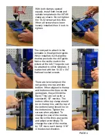
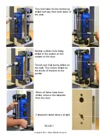
With both clamps opened 
equally, install both inside and 
outside templates to the HIT-66 
clamp as shown. Do not tighten 
the 10-32 screws at this time. 
When all screws have been 
loosely installed, then it is ok to 
tighten. 

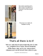
There are two clamps on the 
rod guides, one top and one 
bottom. When aligned to the top 
and bottom scribe lines on the 
guide plate, they will limit the 
travel. They are set up for a 
standard 6-1/2” mortise. The 
bottom of the top clamp should 
be on the top line, and the top of 
the bottom clamp should be on 
the bottom line. Tighten the 
screws when adjusted. To 
change the size of the mortise, 
use the scribe lines as a guide 
and adjust accordingly. To 
change the size of the mortise 
by 1/8” move each clamp 1/16” 
in the desired direction. 

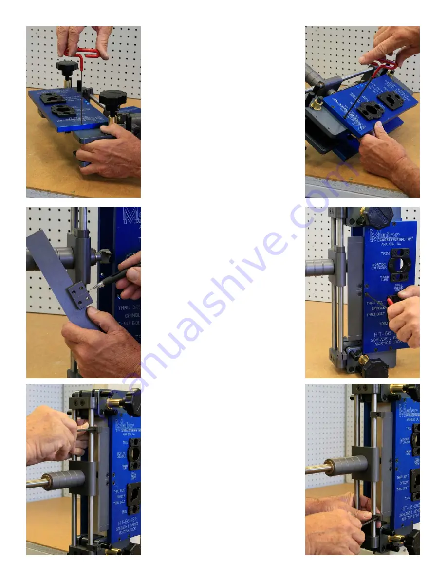
The next part to attach to the 
template is the alignment guide. 
When installed, it will align the 
mortise pocket to the drill guide. 
Notice the scribe mark in the 
picture at the left. The guide can 
be attached to either template, it 
is attached with two 10-32 x 3/4” 
flat head socket screws.  

PAGE 4 

Summary of Contents for HIT-66-200

Page 1: ...200 LOCK MORTISER 1825 VIA BURTON ANAHEIM CA 92806 714 772 5202 FAX 714 772 2302 EMAIL MAIL MAJORMFG COM WEB WWW MAJORMFG COM WHEN USING POWER TOOLS ALWAYS WEAR EYE AND EAR PROTECTION Copyright 2012...

Page 2: ...ow how to safely use the power tools involved Be sure all bits and cutters are sharp and in good condition and all power tools and extension cords are in good working order and properly grounded AND M...

Page 3: ...on top and two on the bottom Leave all screws loose at this time Once all screws have been installed they can be tightened Slide the mortise bit into the unit and slide the stop collar on the end of t...

Page 4: ...The bottom of the top clamp should be on the top line and the top of the bottom clamp should be on the bottom line Tighten the screws when adjusted To change the size of the mortise use the scribe li...

Page 5: ...the bit to the door edge and measure the depth that you want to drill Tighten the stop collar this will limit the depth of the mortise pocket Attach a drill motor to the cutter shaft and tighten the c...

Page 6: ...acturing Inc When the pocket has been completed the lock function holes can be drilled Make sure the mortise bit has been pulled out of the pocket The template shown is for a Schlage Mortise Lock most...

Page 7: ...eing drilled to the pocket on the outside of the door Thumb turn hole being drilled on the right This hole is drilled on the inside of the door to the pocket PAGE 7 Copyright 2012 Major Manufacturing...

Page 8: ...his was the original layout line that we drew in the beginning It can be used to center one of our router jigs to route the faceplate opening Visit our web site at www majormfg com to see our complete...

Reviews: