4
GENERAL DESCRIPTION
●
The range of high Voltage Phase Comparators have been designed
to
comply with and exceed
the requirements of
VDE0681Part5
.
●
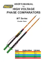
The Phase Comparators are double pole devices which are
used to determine the correct Phase Relationship between
two energized conductors of the Same nominal Voltage and
frequency.
●
Models are available to cover system voltages from
1kV to 44kV
50/60Hz.
●
For other system voltage, please contact the factory.
●
All models may be used indoor and outdoors in
dry weather only
.
●
Meets IEC 61481 (excludes MT44kV)
PRINCIPLE OF OPERATION
●
The MT range of Phase Comparators are resistive devices which
comprise mainly of resistors, a neon and a panel meter. The Phase
Comparator draws current from the circuit or source under test.
●
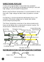
The Phase Comparator consists of two inter-connected poles (the
master pole with the panel meter and the slave pole).
●
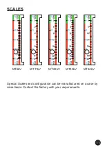
The Master pole carries the panel meter with the colour coded
scale and the integrated neon light indicator.
●
The colour coded scale indicates "in-phase/out-of-phase" band on
the scale. (Green = in-phase; Red=out-of-phase).
●
The Neon light lights up when the voltage between the poles is
greater than ±1.2kV ±1.5kV.
●
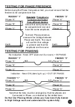
If two energized conductors are out-of-phase and a contact
electrode is touched onto each pole, current will flow between the
conductors through the resistors (resistors are inside the fiberglass
front end in each pole) in the poles and the interconnecting lead/
cord. This will cause the neon to illuminate and the panel meter's
indicator to move into the out-of-phase area (Red).
●
If two energized conductors are in-phase and a contact electrode
is touched onto each pole, current will not flow between
the conductors through the resistors in the poles and the
interconnecting lead/cord. This should not cause the neon to
illuminate and the panel meter's indicator to move. The indicator
will stay into the in-phase area (Green).
●
Ensure that voltage is present on both phases before testing
between phases.

