9
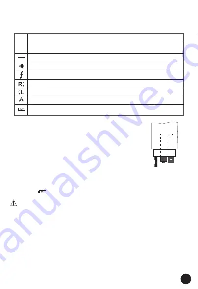
4. EXPLANATION OF SYMBOLS
DC voltage
AC voltage
DC voltage negative potential (DC)
Phase display from 100 to 690V - 50/60Hz
when used as a "single-pole" phase tester. Continuity test symbol
Rotating field display clockwise
Rotating field display anticlockwise
Device for work to be performed with voltage present
Battery replacement symbol
DC
AC
The voltage tester shows the following symbols:
5. INSERTING/CHANGING THE BATTERIES
The voltage tester is operated with two micro-batteries
(type AAA, in the scope of delivery).
Proceed as follows to insert or change the batteries:
• Loosen the screw on the battery compartment lid
(10) with a suitable screw driver and remove it.
• Insert two batteries (AAA) into the battery compartment.
Observe the polarity information in the battery
compartment. If possible, use alkaline batteries. They guarantee a
longer service life. Then, carefully close and screw down the battery
compartment lid again. The batteries need to be changed if the
"Low Bat " symbol lights up on the LCD display or when the LCD
display stays dark after contacting both test tips.
The voltage tester will show no reading if the batteries are flat. The
device must not be operated with flat batteries or without batteries.
To prevent damage to the device from leaking batteries, remove the
batteries from the device if you will not be using it for a longer period.
For the same reason, we recommend that you remove flat batteries
immediately.
6. MEASURING POINT LIGHTING
The voltage tester has a battery-operated measuring point lamp. Press
button (9) to switch this lamp on. The lamp stays on as long as this
button is kept pressed. When the button is released, the lamp goes off.
The lighting button is arranged in such a way that it can also be pressed
during low impedance measurements.
Summary of Contents for MT476
Page 1: ...INSTRUCTION MANUAL 690V VOLTAGE TESTER MT476...
Page 2: ...2...
Page 14: ......
Page 15: ......


