

56, chemin de la Flambère · 31300 Toulouse · FRANCE · T é l . 3 3 ( 0 ) 5 6 1 3 1 8 6 8 7
F a x 3 3 ( 0 ) 5 6 1 3 1 8 7 7 3 · commercial@majorcom.fr · www.majorcom.fr
56, chemin de la Flambère · 31300 Toulouse · FRANCE · T é l . 3 3 ( 0 ) 5 6 1 3 1 8 6 8 7
F a x 3 3 ( 0 ) 5 6 1 3 1 8 7 7 3 · commercial@majorcom.fr · www.majorcom.fr
2
3
EMAGP16
EMAGP16
Usermanual V1.1
Usermanual V1.1
INDEX
1.
IMPORTANT REMARK .................................................................................................3
2.
IMPORTANT SAFETY INSTRUCTIONS ......................................................................3
3.
IMPORTANT NOTE ......................................................................................................5
4.
INTRODUCTION ................................................................................................... 5
5.
INSTALLATION ...................................................................................................... 6
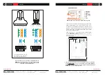
5.1.
Installation with ePXN1616 matrix ................................................................... 6
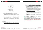
5.2.
Installation with PXN88 matrix ......................................................................... 9
5.2.1.
Installation and wiring
.............................................................. 9
5.2.2.
Compatibility terms and external power supply requirements
.................12
6.
OPERATING THE UNIT ..............................................................................................14
1.1
SENDING MESSAGES ........................................................................................ 14
1.2
DISPLAY AND USER KEYS .................................................................................14
1.3
LED INDICATORS ................................................................................................15
1.4
PRIORITIES FOR SENDING MESSAGES ...........................................................16
7.
NOTES........................................................................................................................18
8.
PART NAMES .............................................................................................................19
9.
TECHNICAL SPECIFICATIONS .................................................................................20
10.
BLOCK DIAGRAM ...................................................................................................21
11.
CONFIGURATION DIAGRAM .................................................................................22
12.
PACKAGE CONTENTS ...........................................................................................23
1.
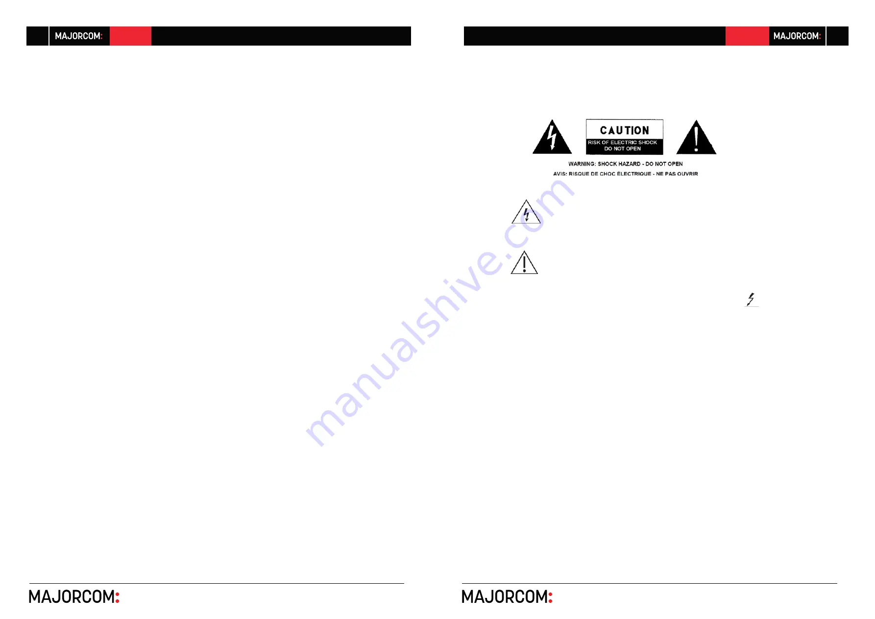
IMPORTANT REMARK
The lightning flash with arrowhead symbols, within an equilateral triangle,
is intended to alert the user to the presence of uninsulated “dangerous vol
-
tage” within the product’s enclosure that may be of sufficient magnitude
to
constitute a risk of electric shock to persons.
The exclamation point within an equilateral triangle is intended to alert the
user to the presence of important operating and maintenance (servicing)
instructions in the literature accompanying the appliance.
WARNING (If applicable):
The terminals marked with the symbol of “
” may be
of sufficient magnitude to constitute a risk of electric shock. The external wiring connec
-
ted to the terminals requires the installation by an instructed person or the use of ready-
made leads or cords.
WARNING:
To prevent fire or shock hazard, do not expose this equipment to rain or
moisture.
WARNING:
An apparatus with Class I construction shall be connected to a mains
socket-outlet with a protective earthing connection.
2.
IMPORTANT SAFETY INSTRUCTIONS
1.
Read these instructions.
2.
Keep these instructions.
3.
Heed all warnings.
4.
Follow all instructions.
5.
Do not use this apparatus near water.
6.
Clean only with dry cloth.
7.
Do not block any ventilation openings. Install in accordance with the manufacturer’s
instructions.


