


56, chemin de la Flambère · 31300 Toulouse · FRANCE · T é l . 3 3 ( 0 ) 5 6 1 3 1 8 6 8 7
F a x 3 3 ( 0 ) 5 6 1 3 1 8 7 7 3 · commercial@majorcom.fr · www.majorcom.fr
56, chemin de la Flambère · 31300 Toulouse · FRANCE · T é l . 3 3 ( 0 ) 5 6 1 3 1 8 6 8 7
F a x 3 3 ( 0 ) 5 6 1 3 1 8 7 7 3 · commercial@majorcom.fr · www.majorcom.fr
12
13
EMAGP16
EMAGP16
Usermanual V1.1
Usermanual V1.1
•
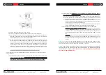
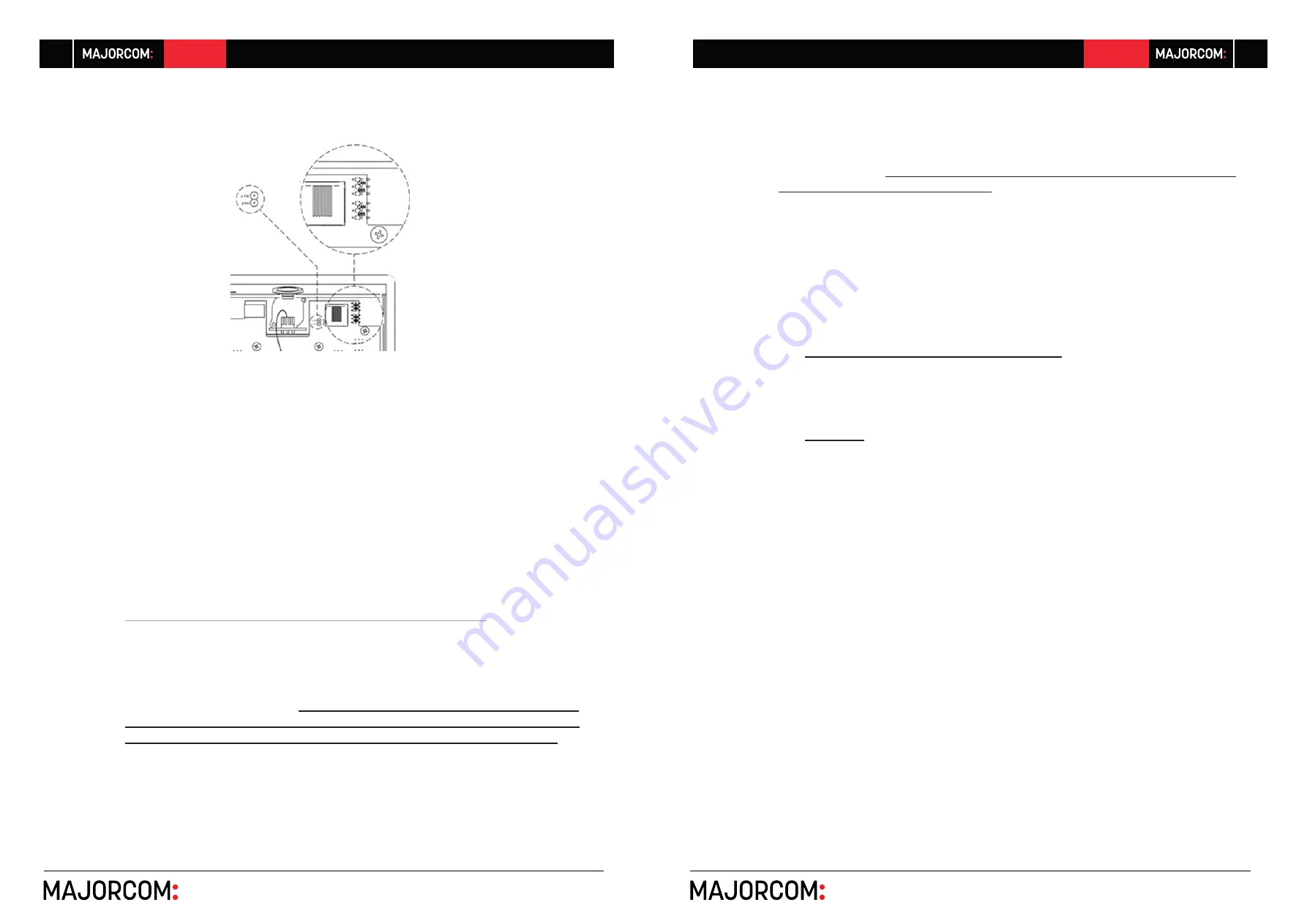
Screw the back cover back onto the unit chassis.
•
Insert the supplied microphone into the XLR connector on the front panel
•
Program the operation and settings of the paging console unit from the PAGERS/DUC
-
KERS tab of the PXN matrix in the MAJORCOMNet Manager project (see MAJOR
-
COMNet Manager manual for extended information)
•
For maximum sound quality and minimum background noise, use a screwdriver to set
the ADJ control on the side of the unit to a high level (increase it by turning clockwise)
and the GAIN control in the affected input of the PXN matrix in the MAJORCOMNet
Manager project (the input to which the audio of the paging station microphone is
connected to) to a low level. You can start from a state with ADJ to maximum and
GAIN to a minimum and adjust them following the above indications until you get
the desired signal levels to broadcast the paging messages in the destination zones.
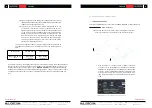
5.2.2. Compatibility terms and external power supply
requirements
It’s possible to connect several EMAGPE16units to the same PXN matrix, considering the fol
-
lowing conditions:
•
Each EMAGPE16unit needs a minimum DC supply of 8V (measured locally, at the unit’s DC
input terminals) to work properly.
A console with a measured DC supply (coming
from the PXN88, PXN88SG or PXN1212SG matrix REMOTE port DC wiring)
lower than 8 VDC will always need an external WP24-PSU power supply.
•
Generally speaking, the
REMOTE port(s) of a PXN matrix can directly feed DC supply
to a maximum of 2 EMAGPE16units
, but when wiring distances are really long, the
inrush current peak when the system is powered ON may result on the EMAGPE16units
not working (blocked, unsuccessful power up sequence) and CAN bus errors detected
in the PXN matrix (registered in the log report in MAJORCOMNet Manager):
o
Cable qualities and conditions may vary a lot and make it difficult to predict with
precision whether a distant EMAGPE16unit may work properly or not with direct
DC supply from the PXN matrix REMOTE port
o
The DC voltage measurement (minimum 8 VDC) will be the only trustworthy me
-
thod to troubleshoot a dubious case and decide to apply a solution.
•
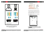
To resolve the above limitation, two possible countermeasures may be applied
o
Option 1 - 100% reliable, always working
: the addition of external power
supplies (
WP24-PSU model
) connected to the EMAGPE16units which do need
it. EMAGPE16units with direct supply from the REMOTE ports of the PXN matrix
and others with external power supply can coexist in the same CAN bus wiring
line
o
Option 2:
use the spare NC (Not Connected) twisted pair in the Cat5 cable to
double the DC supply line wiring from the REMOTE port in the PXN matrix to the
EMAGPE16unit, thus reducing the wiring line resistance and DC voltage drop
along it
Note 1:
a hot connection of a new EMAGPE16unit to a working PXN system (with the system
powered ON) may result in a reboot sequence of other digital remote controls attached to it, taking
some seconds to recover the normal working conditions of them all.
Note 2:
WP24-PSU is the optional external power supply compatible with the EMAGPE-
16paging console. WP-PSU model is the one compatible with the MPAGE16 paging sta-
tion and WPTOUCH digital control.
Never use one of these two power supplies with
devices not compatible with it.


