

56, chemin de la Flambère · 31300 Toulouse · FRANCE · T é l . 3 3 ( 0 ) 5 6 1 3 1 8 6 8 7
F a x 3 3 ( 0 ) 5 6 1 3 1 8 7 7 3 · commercial@majorcom.fr · www.majorcom.fr
56, chemin de la Flambère · 31300 Toulouse · FRANCE · T é l . 3 3 ( 0 ) 5 6 1 3 1 8 6 8 7
F a x 3 3 ( 0 ) 5 6 1 3 1 8 7 7 3 · commercial@majorcom.fr · www.majorcom.fr
14
15
EMAGP16
EMAGP16
Usermanual V1.1
Usermanual V1.1
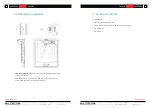
6.
OPERATING THE UNIT
6.1. SENDING MESSAGES
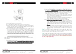
Sending voice messages via an EMAGPE16paging station is done according to the following
procedure:
1.
Visual check of the available/busy status of the zones (LED indicators)
2.
Select the message destination zones by pressing the corresponding keys
3.
Press and hold the PAGE key for the duration of the voice message
4.
Release the PAGE key
5.
Press the CLR (CLEAR) key if you want to cancel the last zone selection.
However, this process and its functional results when sending messages depend on the
programming of the messaging module (PAGERS/DUCKERS) in the ePXN1616, PXN88,
PXN88SG or PXN1212SG matrix unit to which the EMAGPE16paging station is connec
-
ted. This programming is done through the web application embedded in ePXN1616 or
with MAJORCOMNet Manager when used with PXN matrices. Refer to the ePXN1616
Web Application manual / MAJORCOMNet Manager user manual for more information.
6.2.
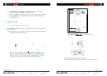
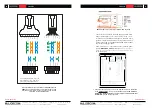
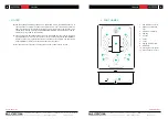
DISPLAY AND USER KEYS
The electronic ink display on the front panel shows the names of the zones enabled for paging.
These names are automatically imported from the names assigned to the outputs of the ePXN1616
or PXN matrix unit to which the EMAGPE16paging station is connected. In the case of zones not
enabled for paging, the display will show “---”.
There are 21 user keys on the front panel of the unit:
•
Keys for selecting the message destination zones. They behave like a “toggle” switch, i.e.
successive keystrokes activate and deactivate the selection of a zone. In the ePXN1616
web application or MAJORCOMNet Manager application (for PXN matrices), the zones
you can send your messages to (zones enabled for each paging station connected to an
ePXN1616 or PXN unit) are programmed, so that non-enabled zone keys are unavailable
from these keys in the paging station.
•
“F1” and “F2” keys: zone group selection keys
•
“ALL” key: selects all zones that are enabled for the paging station (equivalent to pressing
individually all enabled-zone keys)
•
“CLR” key: disables all selected zones, leaving the paging station with no zones selected.
•
“PAGE” key: when pressed and held down, it activates the voice message transmission
function to the selected destination zones. If a “ding-dong” or “chime” melody has
been programmed in the paging station, it is emitted when the PAGE key is pressed,
and it is advisable to wait until it is finished before starting the voice message.
Note:
all functions of the above keys are configured from the ePXN1616 web application or
MAJORCOMNet Manager application (for PXN units).
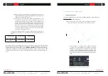
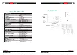
6.3. LED INDICATORS
Two-color LED indicators for zone selection keys (1 to 16). Possible states and their meaning:
•
Unlit: free zone (not used by another paging station or priority module, if any)
•
Lit in green: zone selected by the paging station to broadcast the next message
•
Lit in red: zone not selected in the paging station, but hold by another paging station
or module with higher priority
•
Flashing in orange: zone selected by the paging station, but hold by another paging
station or module with higher priority
•
Lit in orange: the broadcast of a message has been interrupted by another paging
station or priority module, totally or partially, and this lit LED warns the user that
the message has not been fully broadcasted in that destination zone (regardless of
whether it has been broadcasted in other zones or not). The LED status is reset by
pressing the corresponding zone selection key, the ALL key or the CLR key.
•
Temporarily flashing in green: indicates a zone not enabled for selection from the pa
-
ging station
Two-color LED indicators on the PAGE key. Lights while holding down the PAGE key to indi
-
cate that the paging station is in a message send mode:
•
Lit in orange: when you start sending a message (pressing and holding the PAGE key),
it indicates that the chime melody is playing (as determined with the web control appli
-
cation), then turns green when the chime has finished playing. Thus, the speaker knows
when the chime ends and can start its message without the risk of being covered by
the chime
(*)
•
Lit in green: paging function activated, with voice message broadcasting to selected
destination zones


