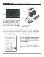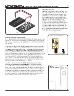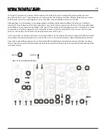
Follow the Arrows!
Aside from the MIDI circuit, the 0-COAST has a 100%
analog signal path with Panel Controls for all of the
parameters that shape the sound. It helps to learn
what each of these circuits does to create, modify,
and modulate the sound. The signal path travels
from the left to right side of the instrument, starting
with the ConTRoL circuits and ending with the
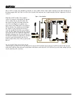
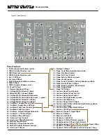
DYNAMICS circuits. If you look at the face of the
0-COAST, you will notice gold wires representing this
signal flow (
Figure 1
). Some of these connections
are always in place, while others are Normalizations,
which means they could be re-routed using patch
cables. These Normalizations are indicated wherever
you see the gold wire terminating in an arrow
pointing to an Input jack (
Figure 17
).
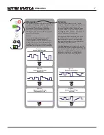
Outside Influence, Control: CTRL
This is where the MIDI, CLOCK, RANDOM VOLTAGE, and CV Processing circuits are
located. These circuits allow for controlling, modulating, and synchronizing the
0-COAST from external sources via the MIDI IN, External CLOCK IN, or TAP TEMPO
functionality.
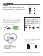
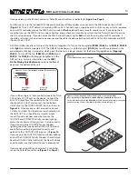
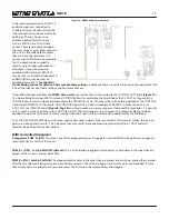
The MIDI Input uses a Mini-Jack connector as opposed to the more traditional
and cumbersome DIN connector. This Mini-Jack connection is very simple and
lightweight if you will be using MIDI from a MIDI device with MIDI on Mini-Jack
such as the Korg SQ1 Sequencer or the Electribe 2. Simply connect the two
devices using a Stereo TRS Mini-Jack cable, as depicted in
Figure 15
. To use the
0-COAST with traditional DIN devices, use the included MIDI Adapter cable. Once
MIDI communication is established (See Getting Started Section), you may want
to customize the MIDI settings for some special use. We have provided two
different ways for users to modify MIDI settings: Local Programming and Sysex
programming. For more information, see the section titled: “Using the 0-Coast
with Other Devices” in the second half of this manual.
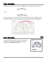
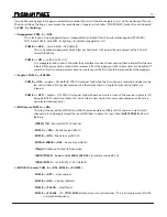
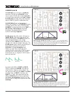
If you follow the gold wire from the
MIDI A CV circuit
, you will see that it is
connected to the
OSCILLATOR PITCH
(
Figure 18
). This wired connection
between the MIDI A circuit and the OSCILLATOR circuit allows for playing the
PITCH of the 0-COAST from a MIDI controller. To hear this, first, set 0-COAST to
the “Default Sound” (
Figure 8
) and then patch your MIDI controller as in
Figure
14
, and then play some keys or send a sequence from your MIDI controller. This
Connection is always in place and may not be re-routed; however, you could
patch a CV Signal to the 1V/Octave input on the OSCILLATOR to control PITCH
from a different source or two sources at once (i.e. MIDI and CV).
14
Figure 17: Typical Normalization Label
Figure 18:
MIDI A CV: Normalizations
Circuits that Create, Modify, and Modulate the Sound
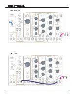
Figure 16: Connecting the Korg SQ-1 to the 0-Coast via CV/GATE Connections


