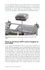
Step 2: Wire up the Flight Controller
Outputs
As we have discussed, the flight controller is nothing more than
a microprocessor that takes an array of inputs, runs calcula-
tions on those inputs, and then sends out the appropriate sig-
nals to keep you airborne. At this point, the only things we have
to wire up to the flight controller are our motors and ESCs (out-
puts). Take a look at the outputs labeled 1–8 on the APM. Notice
that each output has three header pins that are vertically
stacked under the number that labels it. Those three pins are
for the signal, power, and ground found in each servo lead on
your ESCs. They are even labeled on the right of the pins (S, +,
-); look directly at them from the back of the unit.
Wire Color Standards
The three-wire standard that you see on the your ESC is some-
times called a
servo wire
. This always contains a power, signal,
and ground wire with the female header connector that you see.
What can change is the color of the wires. As a rule of thumb,
the power will
always
be red, but the other colors can fall under
one of two styles. They will either be black = ground/white =
signal, or brown = ground/orange = signal. Learning this now
will save you headaches down the road.
Outputs 1 and 2 are for the NE and SW motors, respectively.
Identify the speed controller that handles each motor, and plug
the servo lead from that ESC into the appropriate output port.
Make sure that all ground (black) wires are at the bottom of the
servo lead when plugged in. Repeat this step, adding the NW
motor to output 3, and SE motor to output 4. This is clearly illus-
trated in
86 Make: Getting Started with Drones
Summary of Contents for Belinda Kilby
Page 1: ......
Page 3: ...Make Getting Started with Drones Terry Kilby and Belinda Kilby...
Page 26: ......
Page 90: ......
Page 126: ......
Page 153: ...Figure 9 10 Compass setup Figure 9 11 Compass calibration ArduPilot Mega APM Setup 141...
Page 198: ......


