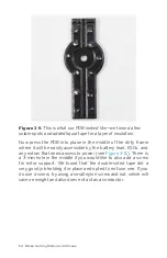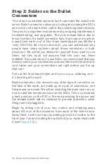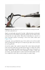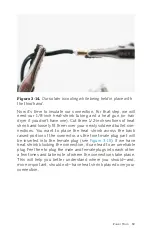
each of their leads, which are carefully insulated with heat
shrink. Now it’s time to do it all over again with the female con-
nectors on the ESCs. Depending on what ESCs you have bought,
there may already be bullet connectors soldered on. If yours do
have connectors in place already, check that they work with
your male motor bullets. If everything seems to connect nice
and snug, skip the rest of this step.
As with your motors, find the three black leads coming out of
your ESCs (not the servo plug, the raw wires), strip about 1/8
inch of the insulation, and prepare the wire for soldering. We are
going to follow the exact same steps that we did for the motors
with the only difference being that we are soldering the female
connectors on this time (see
). Walk back through
the previous steps if they’re not already ingrained in your head
from having done it so many times!
After you have all the connectors soldered up and are ready to
begin insulating them, take note of the difference in area that
needs to be insulated between the male and female plugs.
Rather than the 1/2 inch of heat shrink that you used for the
male plugs, the females will require an inch or more (see
). The heat shrink should go just to the tip of the con-
nector without going over while still extending over the wire on
the other end. Keep in mind that your heat shrink will change
shape a little as it shrinks, so it might pull back from the edge
when you apply heat. We usually position it to stick past the
edge of the connector just a tiny little bit in anticipation of it lin-
ing up perfectly after it has shrunk. If you try this technique and
it sticks out over the edge after it has shrunk, use a razor blade
to carefully cut any parts away that obstruct the male connector
from making a solid connection (see
).
62 Make: Getting Started with Drones
Summary of Contents for Terry Kilby
Page 1: ......
Page 3: ...Make Getting Started with Drones Terry Kilby and Belinda Kilby...
Page 26: ......
Page 90: ......
Page 126: ......
Page 153: ...Figure 9 10 Compass setup Figure 9 11 Compass calibration ArduPilot Mega APM Setup 141...
Page 198: ......


