Step 4: Solder up the Power Supply
The next step is to solder up the power supply. The overall con-
cept here is to connect the positive and negative leads (red and
black wires, respectively) from each of the ESCs in a parallel cir-
cuit. If you aren’t familiar with a parallel circuit, that’s OK. It’s a
pretty simple concept. It simply means that all of the red wires
(positive) are joined together in one connection while all of the
black wires (ground) are on another connection. If you look at
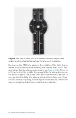
, it becomes very clear how that works. We have one
strip on the board for positive leads and one for ground. All of
the ESCs as well as our main battery lead will connect to the
PDB.
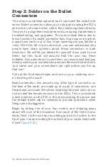
Let’s start with a single ESC as the first example. Take the red
wire coming out of your ESC and determine how long it needs to
be in order to effectively reach a positive circuit on the power
supply (in our case, the left-hand strip). Now clip that wire to
that length (or just a tiny bit longer, just in case) and strip off 1/8
inch of insulation from the tip. Now tin the exposed wire with
your soldering iron and get it ready to be attached to the PDB
(see
).
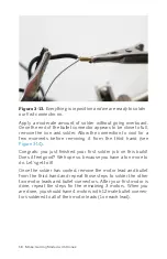
Once you have the positive lead tinned, make sure the tip of
your soldering iron is nice and clean before loading it up with a
little more solder. Next, take your needle-nose pliers and use
them to hold your ESC lead onto the PDB at the point where you
want to make the connection. Make sure you are on the correct
PDB circuit. This is our positive lead, so make sure it’s on the
positive circuit. Finally, apply your hot iron to the top of the posi-
tive lead, sandwiching it between your iron tip and the PDB. If
you have applied enough solder to all the components, they
should all melt together with no problem. Once that happens,
remove your iron while continuing to hold the lead for a few
more seconds with the pliers. If you pay attention to the solder,
you will see it cool in a matter of seconds. It will take on more of
a matte finish look and less of a liquid appearance. Once this
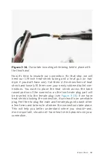
has happened, you can remove the pliers and check the connec-
tion. If it appears to be loose at all, repeat the necessary steps
until you have a solid solder joint (see
).
68 Make: Getting Started with Drones
Summary of Contents for Terry Kilby
Page 1: ......
Page 3: ...Make Getting Started with Drones Terry Kilby and Belinda Kilby...
Page 26: ......
Page 90: ......
Page 126: ......
Page 153: ...Figure 9 10 Compass setup Figure 9 11 Compass calibration ArduPilot Mega APM Setup 141...
Page 198: ......


