background image

Pusher Props

Pusher props earned the name because they were originally

designed for airplanes with rear-mounted motors (like the
Wright brothers’ first airplane) that would push the plane

through the air, rather than pull it from the front. This is very
similar to propulsion in a boat.

Size and Pitch

Propellers have a hub in the center that mounts directly to the
motor, and two (sometimes more) blades that extend out from
the hub. The size is pretty simple to define: it’s measured in
inches from tip to tip on a two-blade prop. For the Little Dipper,
props in the 5- to 6-inch range are ideal, but some drones can
use props up to 29 inches or more!
Pitch is a little more complicated to explain. Most people
wrongly assume that it is a measurement of degrees that the
prop is pointed up from a flat plane. In reality, the pitch is a
measurement of how far the propeller would move forward if it
were passing through a solid matter with one revolution. Think
of the threads on a wood screw. A fine thread will move a shorter
distance with one revolution compared to a coarse thread.
Props work in the exact same way. A higher-pitched prop on the

front of a plane, or even the back of a boat (in theory) would pro-

pel the craft further with one revolution than a lower-pitched
prop. It’s also harder to turn, just like that coarse screw!
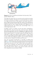
It is outside of the scope of this book to discuss this in much

more detail, but we will mention that the pitch of a propeller is

rarely met in real life (see 

Figure 3-1

). Something called prop slip

always creates a difference between the distance the vehicle
should have moved and how far it actually moved. If you are

interested in that, a ton of websites have a wealth of knowledge

on the topic.

42  Make: Getting Started with Drones

Summary of Contents for Terry Kilby

Page 1: ......

Page 2: ...opter as an example By reading and following the steps and advice contained in this book you ll learn how quadcopters work and how to solve some of the engineering challenges they present Throughout t...

Page 3: ...Make Getting Started with Drones Terry Kilby and Belinda Kilby...

Page 4: ...and Maker Faire are registered trademarks of Maker Media Inc The Maker Media logo is a trademark of Maker Media Inc Make Getting Started with Drones and related trade dress are trademarks of Maker Med...

Page 5: ...et 6 The Smartphone 6 Small Autopilot Flight Controller 6 Principles of Flight 7 Weight Gravity 7 Lift 8 Drag 8 Thrust 9 Flight Maneuvers Aircraft Movement with Stick Mapping 9 Throttle 10 Yaw Rudder...

Page 6: ...der on the Bullet Connectors 56 Step 3 Mount the Speed Controllers 65 Step 4 Solder up the Power Supply 68 Step 5 Mount Brushless Motors 72 Step 6 Connect Brushless Motors 76 Step 7 Clean Up 76 Wrappi...

Page 7: ...structions 116 Step 1 Mount the Ground Station Radio 116 Step 2 Prep the Aircraft Radio for Mounting 117 Step 3 Plug in the Radio 119 Step 4 Mount the Aircraft Radio 119 8 Camera and FPV Equipment 121...

Page 8: ...ght Log Information 166 Aircraft Inspection 168 Flight and Maintenance Logs 168 Laws and Regulations 169 11 Real World Applications 171 Beneficial Drones 171 Aerial Photography 171 Mapping and Surveyi...

Page 9: ...all custom built UAVs The introduction describes how we got started and how our equip ment and work evolved The images are presented in chronolog ical order to show progression in quality as we came t...

Page 10: ...aircraft One chapter covers the intricacies of different airframe types while another dives into how the Global Positioning System GPS is used to assist flight We made a conscious effort to touch on a...

Page 11: ...addresses This element signifies a general note tip or sugges tion This element indicates a warning or caution Safari Books Online Safari Books Online is an on demand digital library that delivers ex...

Page 12: ...Online please visit us online How to Contact Us Please address comments and questions concerning this book to the publisher Make 1160 Battery Street East Suite 125 San Francisco CA 94111 877 306 6253...

Page 13: ...oard computers This definition presents a very broad sense of the word which contributes to the overgeneralizations and misinformation we see when the media reports on a particular type of unmanned ai...

Page 14: ...are a real advantage in pursuing aerial robotics It also helps to be familiar with basic tools and equipment including a soldering iron to have long term success in designing your own small UAVs If y...

Page 15: ...ace to look is the Academy of Model Aeronautics The AMA is the world s largest model aviation association and has been around since 1936 We have a great group of folks here in the Baltimore and Washin...

Page 16: ...958 Jack Kilby a new employee at Texas Instruments and young inventor at the time revolutionized the electronics industry with the introduction of his integrated cir cuit This precursor to the microch...

Page 17: ...user segment The U S Air Force develops main tains and operates the space and control seg ments The system s 36 satellites constantly broadcast a stream of time code and geographical data to users on...

Page 18: ...Currently he is working on a number of different applications in the drone mapping space Small Autopilot Flight Controller All these things GPS the Internet and the smartphone have led to the flight c...

Page 19: ...s laws of physics When we talk about a force what we mean is a simple push or pull If the forces working on an object are balanced a push in one direction met by an equal push in the opposite directio...

Page 20: ...fly level lift must equal weight to climb lift must be greater than weight Figure 1 2 As the airfoil form moves forward through the air it produces lift Drag Have you ever stuck your hand out the wind...

Page 21: ...ciples or forces of flight Flight Maneuvers Aircraft Movement with Stick Mapping Most UAVs are controlled with a standard six channel mini mum remote control just like those that model airplanes have...

Page 22: ...which simply reverses the movements controlled by each stick Many modern radios can use either mode but some are config ured one way only at the factory when they are built Throttle Forward backward m...

Page 23: ...ise props Pitch Forward backward motion of the right stick is the channel for pitch which is also referred to as elevator Pitch tilts the nose of the aircraft up or down When you move the right stick...

Page 24: ...er Maker Camps It is a software disk that comes with an actual remote control that hooks up to your computer using a USB cable There are also several mobile apps including a couple of free ones that y...

Page 25: ...Figure 1 5 Basic quadcopter showing how the stick commands would move the craft Introduction 13...

Page 26: ......

Page 27: ...at they use both clockwise and counterclockwise propellers This is the foundation that allows multirotors to move in all direc tions Every other motor spins in a different direction from the one direc...

Page 28: ...by examining a full size helicop ter The main rotors that spin above the aircraft obviously spin in only one direction The tail rotor provides the counterbalance that keeps the aircraft heading strai...

Page 29: ...flat six Octocopter The octocopter design is often used for aircraft that need increased payload along with redundancy Because it features a total of eight propellers it is possible for an octocopter...

Page 30: ...eristics are important to you There is an old saying in this hobby Cheap strong or lightweight you can have any two While materials like carbon fiber may have a very high weight to strength ratio they...

Page 31: ...ame is made up of two subframes that help isolate the motor vibra tions from the flight and imaging sensors These subframes are called the clean and dirty frames The dirty frame is the bottom subframe...

Page 32: ...which cause vibrations and another to hold everything else We isolate these two subframes by providing the least amount of contact possible between them For the Lit tle Dipper we ship it with four sm...

Page 33: ...n Independent Booms Clean Dirty Frame Folding Booms Lumenier QAV250 250 class quadcopter No No No Blackout Mini Spider Hex 290 class hexacopter Yes No No DroneKraft Mach 300 300 class quadcopter Yes Y...

Page 34: ...eting socket will not work because it is too large The needle nose pliers will mark up your hardware slightly so use those as a last resort Figure 2 5 Tools you will need for the frame build Step 1 In...

Page 35: ...ther aluminum for stiffness and longer life or rubber for increased vibration isolation are used to sepa rate the two subframes Figure 2 7 Pointing out the standoff mounting holes on plate B of the di...

Page 36: ...ld not come out the other side of the standoff if that happens you used the wrong screws When all four are done plate B should look like an upside down table with its legs sticking up in the air as sh...

Page 37: ...because it has longer or wider depending on how you look at it arched boom holes Keep these indicators in mind as you move through the build DroneKraft Mach300 If you are building out a Mach300 your k...

Page 38: ...een both plates If they don t flip one of the plates front to back until the holes match up Why Are Those Holes Arched You may notice that the boom mounting holes shown in Figure 2 10 are made up of o...

Page 39: ...ound hole positioned just above an arched 3 mm slot that allows folding of the frame Figure 2 10 Rear boom mounting holes notice the anchor hole just above the folding slot Let s continue by sandwichi...

Page 40: ...ons between the clean frame and the dirty frames so they should be on the top of the dirty frame top plate plate B Now take your first boom and line the two 3 mm holes on the rectangular end with the...

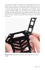
Page 41: ...the way through the sandwiched set of plates push another flat black washer on the other side of it before finally placing a 3 mm locking nut on the bottom Repeat this for the second hole on the boom...

Page 42: ...just enough to hold the boom in place firmly but not so much that it pre vents it from folding at all Practice folding the boom as you are going through this step The nuts we use called lock nuts have...

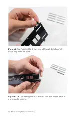
Page 43: ...om of our frame that is held together with the standoffs Let s start by finding plate D You will notice eight 3 mm diame ter holes that are positioned around the edges of the plate These are our stand...

Page 44: ...Figure 2 14 Pushing the 5 mm screw through the standoff mounting holes on plate D Figure 2 15 Threading the first 37 mm standoff on the back of our mounting screw 32 Make Getting Started with Drones...

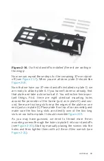
Page 45: ...rst there are eight identical mounting holes around the perimeter of the frame just as in plate D and sec ond there are two long slots near the edges of the plate on one end just as in plate D Place p...

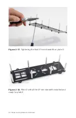
Page 46: ...Figure 2 17 Tightening the final 37 mm standoffs on plate D Figure 2 18 Plate D with all the 37 mm standoffs installed and ready for plate E 34 Make Getting Started with Drones...

Page 47: ...Figure 2 19 Plate E on top of our assembly prior to adding the mounting screws Figure 2 20 Threading our first mounting screw through plate E into our 37 mm standoffs Airframes 35...

Page 48: ...e main differ ence is that the QAV has booms built into its bottom plate and only uses six standoffs to separate the two frame plates This will create a lighter frame that is well suited for racing ap...

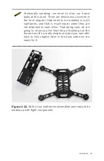
Page 49: ...nd that is much easier when they are not attached to each other That being said we are going to show you the final step of building out the frame now it s a really simple one and you can refer back to...

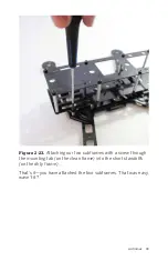
Page 50: ...tick out from the bottom of the clean frame with 3 mm holes in the center with the four short standoffs sticking up from the top of the dirty frame Make sure that both frames are pointing in the same...

Page 51: ...Attaching our two subframes with a screw through the mounting tab on the clean frame into the short standoffs on the dirty frame That s it you have attached the two subframes That was easy wasn t it A...

Page 52: ...era plate This is going to be installed along with the vibration isolation balls later in the book Cameras are discussed in Chapter 8 and we felt that was the best place to explain the details of what...

Page 53: ...ir moving the drone And like tires for your car props come in all shapes and sizes and should be selected according to the rest of the power train that will drive them There are three main specs you w...

Page 54: ...d up from a flat plane In reality the pitch is a measurement of how far the propeller would move forward if it were passing through a solid matter with one revolution Think of the threads on a wood sc...

Page 55: ...rate more lift Typically the higher the pitch and or the larger the prop the more lift that is generated If you have a heavy aircraft or one that needs to fly at high speeds a high pitch or large prop...

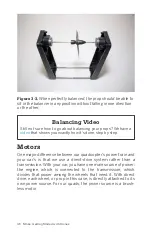
Page 56: ...is passed through the prop at the cost of using more power from the battery Balancing Props Here we find ourselves drawing another parallel between tires and propellers Just as your tires need to be b...

Page 57: ...ically very small adjustments Adding weight might come in the form of a few small clips of Scotch tape or label stickers while subtracting weight is usually done with sandpaper and a bit of patience W...

Page 58: ...otors One major difference between our quadcopter s power train and your car s is that we use a direct drive system rather than a transmission With your car you have one main source of power the engin...

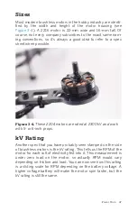
Page 59: ...s are rated at 2300 kV and work with 5 or 6 inch props kV Rating Another spec that you have probably seen stamped on the side of brushless motors is the kV rating This tells us the RPM of the motor fo...

Page 60: ...should use based on the manufacturer s suggestions Total Lift A common term you will hear in relation to motor and prop com bos is their total lift which is the amount of upward thrust a motor prop co...

Page 61: ...flight battery into a sequence of electrical signals that are sent across three differ ent wires to the brushless motor That sequence controls the speed rotation and even braking ability of the motor...

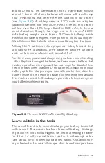
Page 62: ...m polymer Li Po battery Very similar to those used in smartphones Li Po batteries have a much greater capacity to weight ratio than older generation nickel cadmium NiCD and nickel metal hydride NiMH b...

Page 63: ...ch fire For this reason you should always use great care when handling Li Pos Replace damaged batteries and never use a battery that has been punctured in any way that is a recipe for disaster Use fir...

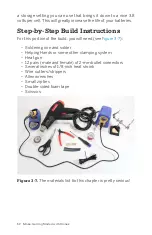
Page 64: ...build you will need see Figure 3 7 Soldering iron and solder Helping Hands or some other clamping system Heat gun 12 pairs male and female of 2 mm bullet connectors Several inches of 1 8 inch heat shr...

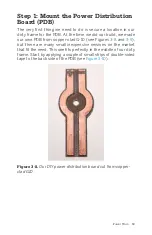
Page 65: ...PDB from copper clad G 10 see Figures 3 8 and 3 9 but there are many small inexpensive versions on the market that fit the need This one fits perfectly in the middle of our dirty frame Start by apply...

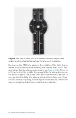
Page 66: ...battery lead ESCs and any extras that need access to power see Figure 3 11 There is a 3 mm hole in the middle if you would like to also add a screw for extra support We found that the double sided tap...

Page 67: ...Figure 3 10 Applying double sided tape to the back side of the PDB Figure 3 11 The PDB is pressed firmly into place Power Train 55...

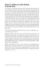
Page 68: ...them we recommend that you directly solder your connections and seal them with heat shrink Just make sure your connections are right before you fire up that iron Pull out the third hand helper and tur...

Page 69: ...Next we are going to get out our third hand and use it to add the male bullet connectors to our motor leads Clamp one bullet connector into one of the alligator clips with one of the tinned motor lea...

Page 70: ...Congrats you just finished your first solder job on this build Does it feel good We hope so because you have a ton more to do Let s get to it Once the solder has cooled remove the motor lead and bulle...

Page 71: ...t con nections You want to place the heat shrink across the back raised portion of the connector as the front male plug part will be inserted into the female plug see Figure 3 15 If we have heat shrin...

Page 72: ...specially if you are new to this process If you are using a hair dryer or heat gun with a lot of wind displacement be careful that the moving air does not move your carefully posi tioned heat shrink A...

Page 73: ...eat gun to shrink our tubing for insula tion purposes Figure 3 17 The finished product We are starting to make some real progress At this point you have four motors with bullet connectors firmly solde...

Page 74: ...ined in your head from having done it so many times After you have all the connectors soldered up and are ready to begin insulating them take note of the difference in area that needs to be insulated...

Page 75: ...Figure 3 18 Soldering up our first female bullet connector Figure 3 19 Be sure to cut the heat shrink to the right length for the female connectors Power Train 63...

Page 76: ...point we have four motors with male bullet connectors and four ESCs with female bullet connectors If you haven t done so already let s try plugging them into each other and see how they fit see Figur...

Page 77: ...fold on this particu lar frame we will be mounting the speed controllers on the inside of the dirty frame Use double sided tape to mount the speed controllers Apply a small strip about 1 2 inch wide t...

Page 78: ...und where we installed our PDB Try to mentally separate this into quadrants and place each ESC into its own space The red and black power leads coming off the ESC should be pointing toward the center...

Page 79: ...e 3 24 Position the ESC and then press it firmly into place making sure there is enough space below it for another unit Figure 3 25 When all of the ESCs are in place it should look like this Power Tra...

Page 80: ...n from the tip Now tin the exposed wire with your soldering iron and get it ready to be attached to the PDB see Figure 3 26 Once you have the positive lead tinned make sure the tip of your soldering i...

Page 81: ...Figure 3 26 Tinning our first ESC power lead before attaching it to the PDB Figure 3 27 Our first lead is soldered and seems to be a solid connection Power Train 69...

Page 82: ...lead in the same fashion mak ing sure you connect it to the negative circuit seen here on the strip closest to the bottom of the image Awesome your first ESC is connected to the PDB Now do the rest i...

Page 83: ...Figure 3 29 Our first ESC is all ready to get power from the PDB Figure 3 30 Example of another build from our fleet with all the ESCs connected to the PDB Power Train 71...

Page 84: ...omething like a video transmitter all you have to do is pull that plug out and tap into your power right there No need to get the soldering iron out again Step 5 Mount Brushless Motors Brushless motor...

Page 85: ...with a standard thread One catch not all manufacturers make their motors this way Many still only use a standard thread on all of their motors This will still work fine just be sure to tighten it well...

Page 86: ...he bottom of the motor Once the first one is done feed the opposite screw in and keep going until you have all four in place see Figure 3 32 Once you have all of the screws manually fed into place tig...

Page 87: ...2 Feed the screws in the same way you would a set of lug nuts on a car to ensure an even tightness all the way around Figure 3 33 Tighten the screws turn for turn to ensure that they are all even Powe...

Page 88: ...ing to damage the motor it will simply spin in one direction or the other Our ultimate goal is to make the NE and SW motors spin in a counterclockwise direction But because our build is not com plete...

Page 89: ...ers and motors permanently mounted Make sure everything is firmly mounted with little risk of coming loose Also check all soldering in your power harness power distribution board to make sure nothing...

Page 90: ......

Page 91: ...per second for each of the motors in order to achieve said command If the drone encounters some type of resistance such as a headwind the flight controller will attempt to make up the difference neede...

Page 92: ...aft and the air pressure which can often be con verted to the aircraft s altitude These three sensors provide all the data that the autopilot needs to keep the aircraft stable in the air Additional se...

Page 93: ...2C protocol We will be using this port for our external compass PM This is our power module port This allows us to monitor our power supply JP1 This is a jumper port used to tell the APM if there shou...

Page 94: ...software assistants are more robust than others they all generally control the aircraft configuration communications setup and autolevel gains Software assistants can connect through Bluetooth USB or...

Page 95: ...Controller The APM flight controller will be mounted on the bottom plate of the clean frame Use two small pieces of double sided tape at either end of the flight controller to attach it firmly to the...

Page 96: ...ng holes These will appear on both the top and bottom plates of the clean frame Another indicator is that the booms fold backward on the frame Yet another indicator is that the large hole that the cam...

Page 97: ...lace each portion at one end of the APM then peel off the backing Figure 4 5 With the adhesive tape exposed position the APM in the center making sure it is pointing in the right direction and firmly...

Page 98: ...Wire Color Standards The three wire standard that you see on the your ESC is some times called a servo wire This always contains a power signal and ground wire with the female header connector that yo...

Page 99: ...t below the plugs This will help keep everything neat and organized Now push that group of cables through one of the four rectangular holes in the back of the clean frame near the APM output pins See...

Page 100: ...s removed so we could get a better photo it is not required to do this If you are using a flight controller other than the APM check your instruction manual for the proper motor output sequence APMs a...

Page 101: ...o ahead and attach the two subframes to each other If you remember we covered this step at the end of Chapter 2 while we were building out the frame If you don t recall this step refer back to Step 4...

Page 102: ...have our flight controller firmly mounted to the clean frame and have outputs going to the four motors Double check all connections and make sure that the appropriate wires are going into the appropr...

Page 103: ...three in a single chapter GPS One feature clearly draws the line between a drone and a model aircraft the ability to operate using GPS see Figure 5 1 The addition of this satellite navigation technol...

Page 104: ...properly configured The same approach is taken with altitude Altitude hold is usu ally within plus or minus three meters and can use additional sensors beyond just GPS such as the internal barometer...

Page 105: ...attempting to fly via waypoints If the craft can hold position and RTH safely it should be more than capa ble of waypoint flight Is My GPS Working Correctly One nice way to tell how accurate your GPS...

Page 106: ...r demo build the compass tells our drone not only where all the cardinal directions lie but also which direction it is pointing to upon startup and any changes that happen during its flight Is It Real...

Page 107: ...enclosure If you have an APM 2 5 don t fret There is a fairly simple way to disable the internal compass and take advan tage of the newer external units Battery Monitor Another small but very importan...

Page 108: ...a certain voltage is reached as a failsafe measure Step by Step Build Instructions The following steps will walk you through the installation of the GPS compass and battery monitor While this portion...

Page 109: ...a best practice to place the GPS puck with internal compass high above the rest of the electronics to avoid any magnetic interference Follow any assembly instructions that came with your mounting bra...

Page 110: ...ore small cables that allow you to connect it to the APM Remove them from the bag and inspect them carefully This GPS is able to work with a few different autopilot systems so it will likely ship with...

Page 111: ...with your compass tell your vendor imme diately especially if you bought the APM and GPS together from the same store Figure 5 5 Make sure that you have the right cables for the job Now that we have...

Page 112: ...sition cable see Figure 5 6 Figure 5 6 The two ports on the side of our GPS puck MAG Port In case you haven t figured it out on your own the MAG port on the side of the GPS puck is labeled as such bec...

Page 113: ...d plug it into the GPS port on the APM next to the forward arrow on the top Now take the remaining 4 position plug and insert it into the I2C port short for inter integrated circuit and pro nounced I...

Page 114: ...ould be inserted into your component All cables being inserted into the APM unit itself will always have the single red wire on the right hand side as determined by the ports text label Oddly enough w...

Page 115: ...in on the bench Figure 5 8 Our battery monitor plugged in on the bench speak ing to the APM over a 6 position cable that plugs into the PM port Start off by plugging the battery monitor into the main...

Page 116: ...d snug with the monitor lying across the bottom of the clean frame Be sure to route the 6 position cable across the bottom of the frame in through the same holes that you routed the ESC plugs earlier...

Page 117: ...Figure 5 10 Getting our battery monitor into position and ready to be fastened to the frame Figure 5 11 The new battery lead is accessible to the flight battery GPS Compass and Battery Monitor 105...

Page 118: ...cable is on the right side as indicated by the port label Wrapping Up That s it for the GPS compass and battery monitor Later in the book we will use the flight controller software to confirm that the...

Page 119: ...in see Figure 6 1 The transmitter is the remote control for your aircraft You can use the transmitter to send commands to your aircraft by manipu lating any of its sticks sliders buttons or switches...

Page 120: ...we will discuss in greater detail in Chapter 8 It is impor tant to know exactly which frequency bands you are operating on because flying in groups where conflicting frequencies are duking it out for...

Page 121: ...the documentation for both your receiver and autopilot to know which protocol you should use If PPM is available we highly suggest that you use it because it will clean up your install dramatically w...

Page 122: ...eries of cables in between the receiver and the autopilot Because of the differences between PWM and PPM as well as different manu facturer standards there are dozens of different connection scenarios...

Page 123: ...out for the vibration isolation mount that the camera will sit on Another good reminder is that the booms fold back on the frame not forward Step 2 Mount the Receiver Use a piece of the thick foam do...

Page 124: ...idea to keep as little airframe as possible between the receiver and the controller on the ground If your receiver has long antenna wires run them out of the frame and as low as possible to provide th...

Page 125: ...channel input 4 to the yaw channel and finally input 5 to Aux 1 We will use this channel to switch among our different flight modes Figure 6 5 PWM wiring schematic for APM Transmitter 113...

Page 126: ......

Page 127: ...d can be illegal in certain parts of the world Be sure to check the laws in your country to see what standard you should use Just as its name implies the telemetry link takes a series of measurements...

Page 128: ...tape One inch of Velcro Zip ties Step 1 Mount the Ground Station Radio Your telemetry radio set will actually come with two different radios One goes on the aircraft while the other connects to your...

Page 129: ...based PCs If you are using a Mac laptop check out APM Planner It is very similar to Mission Planner but it s cross platform with builds available for Windows OS X and Linux Step 2 Prep the Aircraft Ra...

Page 130: ...it s not mounted yet Figure 7 3 Double sided foam tape can be used to fasten the radio to the air frame Which Way Is Up Be sure that you are mounting these components in the correct spot You can easi...

Page 131: ...al The other end of that cable will plug into the telemetry port on your autopilot Figure 7 4 Plugging in the telemetry radio will be much easier if done before it s mounted to the frame Step 4 Mount...

Page 132: ...e sides of the cable plugs that allow the cable to plug in in only one direction Find those tabs and identify the direction before applying pressure see Figure 7 6 Figure 7 6 Guide tabs on the side of...

Page 133: ...for when selecting a new camera for any of our drones are Weight and size As with every other component in the drone world weight is always one of the first qualities to consider It is always more de...

Page 134: ...it meets your needs Cost After you ve whittled down the list of potential candidates using the first four qualities it s time to look at price Prices can range within each category so do some researc...

Page 135: ...f focus photos This also produces images with brighter corners and better overall off center resolution Basi cally with a four thirds camera you can achieve high quality photos with a relatively small...

Page 136: ...rams depending on model purchased Internal rechargeable Li Po battery no need to connect it to the aircraft s power system Full HD video at 1080p 30FPS 720p 60FPS for slow motion HD video Still photo...

Page 137: ...ream from your camera and broadcasts it over a specific frequency range to a receiver or rTX on the ground The receiver then connects to a monitor or video goggles to display the live feed Figure 8 3...

Page 138: ...we are going to continue down that build path and will not be reviewing further info on FPV However if you are interested in learning more about how to install a video transmitter or other FPV gear f...

Page 139: ...off of smaller plastic parts such as our quick release cam era mount Take your time and make sure that you line the camera mount up nice and straight on the vibration isolation plate If you don t it...

Page 140: ...do this is by using a piece of thread or unwaxed dental floss to pull the ball mounts through the mount ing holes as shown in Figure 8 6 Repeat this step for all four rubber balls Are You Facing the...

Page 141: ...is slide the camera into the camera mount see Figure 8 7 Make sure that the lens of the camera is pointing away from the camera mount then line up the small groove that runs around the middle of the...

Page 142: ...Figure 8 7 Mobius camera next to the quick release camera mount 130 Make Getting Started with Drones...

Page 143: ...s For this portion of the build you will need A laptop PC running Windows 7 or newer if you only have a Mac try setting up a Boot Camp partition to install Win dows The most recent version of the Miss...

Page 144: ...onfirm that you do want to update the firmware Click Yes to continue see Figure 9 2 f Mission Planner will locate the most recent version of the APM firmware that is available for your hardware and st...

Page 145: ...Figure 9 2 Confirm that you want to upgrade by clicking YES Figure 9 3 Mission Planner automatically finds the most recent firmware version supported by your APM ArduPilot Mega APM Setup 133...

Page 146: ...Figure 9 4 Firmware upload has begun Figure 9 5 Firmware verification in progress 134 Make Getting Started with Drones...

Page 147: ...proper baud rate at which your communi cations should travel This defines the bits per second for data communication The general rule of thumb is to use 115200 for communications over a USB cable and...

Page 148: ...al process in this example but both ways are essentially the same thing the wizard just forces you to do all the steps together while manual entry allows you to do only the steps you want Any time we...

Page 149: ...fault settings for our model so we have to set them up manually That s OK you learn more doing it that way Figure 9 7 Select frame type X Versus When we selected the X frame type you probably noticed...

Page 150: ...el as possible If you have one use a bubble level to confirm that the area you have selected is not out of level We often use a small TV table because it is easy to shim up to level if it s off a litt...

Page 151: ...ed straight down toward the ground with the tail sticking straight up Nose up The tail of the aircraft pointed straight down with the nose pointed straight up Left The left side of the aircraft pointi...

Page 152: ...ss option This should change the text at the bottom of that field to say ROTATION_ROLL_180 This information tells the APM what direction the compass is pointing in so it has a baseline to start its me...

Page 153: ...Figure 9 10 Compass setup Figure 9 11 Compass calibration ArduPilot Mega APM Setup 141...

Page 154: ...radio see Figure 9 13 a If you haven t done so already power up your radio transmitter b Click the green Calibrate Radio button under the Radio 8 bar graph in the main application window c When direct...

Page 155: ...Figure 9 12 Prior to starting the Radio Calibration process Figure 9 13 Notice the red lines that indicate the min max value for each channel ArduPilot Mega APM Setup 143...

Page 156: ...l flight mode such as Auto waypoint navigation or RTH return to home a With the radio powered on toggle through the different posi tions on your flight mode switch while watching Mission Planner You w...

Page 157: ...itch position 2 and assign Stabilize with that mode menu see Figures 9 16 and 9 17 Figure 9 15 Switch position 1 lighting up flight mode menu 2 Figure 9 16 Switch position 2 lighting up flight mode me...

Page 158: ...Battery field on the right side of the main applica tion window Set the Low Battery option to 10 4 and the Reserved MAH to 0 This allows us to monitor only the volt age and not the capacity of the bat...

Page 159: ...he APM what to do any time the radio connection is dropped for a certain amount of time as decided by APM Now set the FS PWM text field to a value of 975 This tells APM what the PWM value should be du...

Page 160: ...battery monitors but there is a long list of additional options including sonar sensors airspeed monitors optical flow sensors on screen display OSD camera gimbals servo based antenna trackers and Blu...

Page 161: ...o check that your radios are communicating with each other as expected a Make sure that you are not already connected to Mission Planner over USB If so disconnect and unplug the cable b Power up your...

Page 162: ...mall chip that communicates with the APM to analyze the current draw and capacity remaining in the battery This page in Mission Planner allows you to adjust the few settings for the battery monitor To...

Page 163: ...ion This is pretty self explanatory For this build select the APM 2 5 3DR Power Module option If you purchased a different flavor of APM such as the Pixhawk or PX4 then find your model in the options...

Page 164: ...Geo Fence can be a pretty cool safety feature for new pilots It does exactly what its name implies it sets up a virtual fence around your takeoff point that you are not allowed to fly beyond Think of...

Page 165: ...35 lb Octocopter with a DSLR under it Tuning allows you to use the same autopilot in both aircraft but alter it to work in either environment Basic Tuning is the entry point to tuning your APM see Fig...

Page 166: ...ou adjust each of the three aircraft movements roll pitch and yaw with variables that feed into a PID controller algorithm This type of controller is very popular in large scale industrial control sys...

Page 167: ...ard Params The Standard Params page starts to show you the extreme flexi bility of the APM platform see Figure 9 26 The screen shows a long list of parameters that can be set to help customize or fine...

Page 168: ...bottom The top portion contains an instrument that may look familiar to you It is essentially an arti ficial horizon just like you would see in a full scale airplane The only difference here is that o...

Page 169: ...e mission to a single waypoint can be planned from this screen No matter what the complexity of your mission they are all made up of a series of waypoints that direct the aircraft to a specific latitu...

Page 170: ...Android tablets to cut down on the amount of gear they need to pack for their flights Tablets can even be mounted directly to the 2 4 GHz radio transmitter in an effort to keep all control systems in...

Page 171: ...change any two of the three bullet connections to reverse the direction 2 With the props still off and the motors spinning in the correct direction check to see if the APM is autoleveling correctly Yo...

Page 172: ...nd creates a disturbance that can push your aircraft around a little bit 4 Take your time and practice This isn t a race and there are no prizes for getting in the air immediately If you take your tim...

Page 173: ...way to learn or gain discipline You must dedicate yourself to being mindful of consistently doing all that is needed to best produce successful and safe results in all possible ways Training and Educ...

Page 174: ...afely flying small UAVs These groups the Association for Unmanned Vehicles International AUVSI the Academy of Model Aeronautics AMA and the Small Unmanned Aerial Vehicles Coalition SUAVC compiled a co...

Page 175: ...ltirotor which assists in maintain ing your orientation See the note below this section on safely flying using FPV goggles Join a local club for UAV or model aircraft enthusiasts If that is not possib...

Page 176: ...erspective of the drone FPV flight is growing fast in popularity thanks to organized competitive minidrone racing The April May 2015 issue of Make magazine is full of great FPV features and informatio...

Page 177: ...ighting features may also be important to you if for no other reason than to ensure you re not looking directly into the sun while visually tracking your UAV The best way to identify potential risks i...

Page 178: ...lites locked in Weather sun direction wind direction and speed Maximum safe wind speeds depend on the weight and design of your aircraft The Little Dipper is very light at 2 lbs so it is best to fly i...

Page 179: ...using rope poles paint or field lining powder is a great way to keep spectators at bay If you have a spotter with you have her talk to anyone nearby to let them know what you are doing to direct spect...

Page 180: ...t on the spot Review battery procedures refer back to Chapter 5 Their age how they are handled and stored and whether they are intact or have unused charge can all have an effect on Li Po batteries Ta...

Page 181: ...ctors led you to make each component selection throughout your build Compare parts or brands you considered and what the result of each decision turned out to be It may seem like an excessive exercise...

Page 182: ...applications is the main common factor around the world to determine which set of rules you should follow United States Federal Aviation Administration FAA Academy of Model Aeronautics AMA Know Befor...

Page 183: ...l explore what we feel are the top real world benefi cial applications for UAV use This list is just the beginning of how drones are helping save time money and lives There is an international competi...

Page 184: ...camera to take pictures at regular intervals say every five seconds or so We have found that a two person team works well to compose the best shots The pilot is able to concentrate on operating the ai...

Page 185: ...mapping The first type is for mission planning and the second is for data pro cessing The UAV flies in a lawnmower pattern autonomously see Figure 11 3 Several mission planning applications are availa...

Page 186: ...needs of a growing population With 2 2 million farms in the Uni ted States alone precision agriculture will benefit immensely from small UAVs Farmers agronomists and farm support ser vice providers ar...

Page 187: ...precisely onto only those crops that need it Successful UAV precision agriculture programs are found in Canada Brazil and Sweden but the standout model is in Japan The Japanese Agriculture Ministry c...

Page 188: ...r filing a petition for review with the US Court of Appeals for the District of Columbia with a complaint against the FAA for wrongly ordering a cease and desist in an email for using UAVs for search...

Page 189: ...ain an extremely clear view of any area techni cians would need to get a detailed look at A live feed allows the inspectors to see in real time what the drone sees High resolution files can then be st...

Page 190: ...anet s endangered species and their habitats They must cover vast arduous to navigate locations Planning expeditions is expensive laborious and time consum ing Conservationists have perished from enco...

Page 191: ...es in real time To do this you will need to add a video transmitter on the aircraft and a video receiver to a ground station with some type of monitor goggles or small screen to view the feed see Figu...

Page 192: ...the scope of this one However if you are interested in the topic and would like to learn more feel free to check out our online FPV page Figure 12 1 5 8 GHz video transmitter with a right angle adapt...

Page 193: ...use this is an open source platform you can even alter the firmware to react to certain sensor input any way you like Per haps you would like to use a wind speed sensor to slow down forward flight onc...

Page 194: ...already learned in this book getting the desired performance requires a fine balancing act among all the components and the design That same theory applies to speed as well The major things to conside...

Page 195: ...try experimenting with different pitched props of that size Battery voltage In Chapter 3 we talked about how you can calculate the RPM of your motors by multiplying the battery voltage against the KV...

Page 196: ...ger flight times Of course decreasing the weight of the aircraft will also gain you a little more flight time so look at that as another option to improve your air time Troubleshooting in the Drone Co...

Page 197: ...thdrones com Thank You Speaking of the online drone community we would like to say thank you to everyone from DIYDrones and MultiRotorForums who has shared any tidbit of information they learned the h...

Page 198: ......
Page 199: ...onitor setup 150 151 baud rates for 135 building 83 87 COM port for 135 compass setting up 140 connecting to Mission Planner 136 FailSafe setup 146 flight data viewing 156 flight modes setting 144 152...

Page 200: ...UAVs aircraft inspection for 168 balancing 19 components of see airframe battery monitor camera compass flight controller power train receiver teleme try radio transmitter flight time of increasing 18...

Page 201: ...f drone development 3 7 I I frame type 137 I2C inter integrated circuit 81 IMU Inertial Measurement Unit 7 infrastructure inspection 176 178 insurance coverage 163 inter integrated circuit I2C 81 Inte...

Page 202: ...ources 162 163 airframe building video 40 APM standard and advanced parameters 155 balancing props video 46 for this book x FPV first person view 180 internal compass disabling 95 laws and regulations...

Page 203: ...or motor 47 48 RTH return to home flight mode 92 144 146 147 rudder see yaw S safety aircraft inspection 168 best practices 3 162 164 first person view FPV 164 importance of 161 insurance coverage 163...

Page 204: ...smitter video 125 126 179 tricopters 17 troubleshooting 184 185 tuning APM 153 154 U UAVs unmanned aerial vehicles vii 1 see also drones universities offering majors in UAVs 171 user community 2 3 184...

Page 205: ...ich she used to attend Maryland Institute College of Art After becoming a young mother she transferred to Salisbury Univer sity and University of Maryland Eastern Shore to earn degrees in art and educ...

Reviews: