47
17. Using user boards
The robot board can be equipped with different user boards to extend the functionality. Possible user boards are e.g., Arduino UNO, NodeMCU or compatible
boards. These can be plugged directly onto the robot board.
With the software library described in the next chapter you can send control commands from the user board to the locomotion controller or read values from
the locomotion controller. More about this later in the next chapter "Demo Programmes".
•
Arduino-UNO
The two outer longer pin headers are used for a compatible user board "Arduino-UNO". All pins are led out at socket connectors next to it. This allows you
to easily access the pins of the board. The pin assignment is printed on the board next to the pin headers and corresponds to that of the board used. Have
a look at the software examples.
•
NodeMCU
The popular WiFi board with the designation "NodeMCU" and the employed ESP8266 WiFi chip can be used on the inner slot as a user board. Also, here all
pins are led out on the adjacent socket strips, which makes experimenting easier. Have a look at the software examples.
•
SBC (Single Board Computer)
A Raspberry Pi 2 or 3 or any other SBC can be connected to the pin header next to the "ISP-U" connection. It is also possible to use radio modules or
Bluetooth
®
modules as user boards via this connection. This pin header should be regarded universal and represents an interface for proper extensions and
developments.
•
Arduino UNO
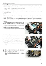
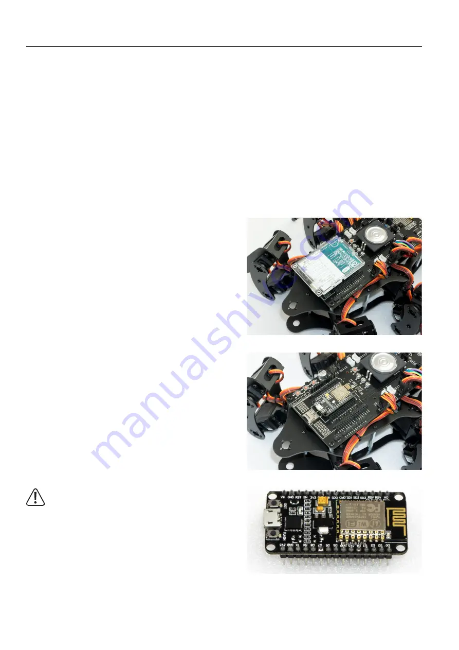
Plug an "Arduino UNO" board onto the robot board as shown in Figure 73. Proceed
carefully and make sure that the longer pin strips, which are plugged into the sockets
of the "Arduino UNO" board, are not bent.
Also, make sure that all pin header pins are plugged into the sockets of the "Arduino
UNO" board.
It is possible to use almost all Arduino UNO compatible boards.
After plugging in the board, you can jump directly to the chapter "Demo Programmes".
•
NodeMCU WiFi Board
The WiFi board called "NodeMCU" and the ESP8266 WiFi chip used can be used as
a user board on the inner slot.
If you want to extend the robot board with WiFi, you can easily do so with the help of
this user board. The examples already include programmes for the NodeMCU board
that allow control view from a web browser.
Plug a NodeMCU board onto the Hexapod Robot Board as shown in Figure 74.
Proceed carefully and make sure that the pin strips are not bent and that all pins are
plugged in correctly.
After plugging in the board, you can jump directly to the chapter "Demo Programmes".
When buying, make sure that the distance between the pin strips is correct!
There are two different versions on the market. One has a Silabs CP2102 as
USB chip while the other version has a CH340G.
The version with the CH340G has a wider pin spacing and does not fit into the
robot board! The NodeMCU board to be used must have a pin strip spacing of
23 mm.
Figure 73
Figure 74
Figure 75
Summary of Contents for 1664151
Page 1: ...Operating Instructions Hexapod Robobug Complete Set Item no 1664151...
Page 23: ...23 The femur servo mount must be mounted a total of 6 times Figure 31 Figure 32...
Page 26: ...26 Figure 37...
Page 36: ...36 Figure 58 Figure 59...
Page 37: ...37 Figure 60 Illustration_61 Figure 61...
Page 38: ...38 Figure 62...
Page 66: ...66...
Page 67: ...67...


