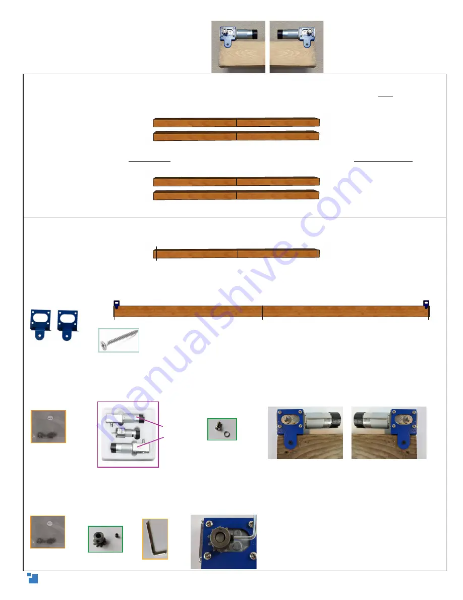
2.
(A)
Measure the actual length of the 2in x 4in x 10ft beams and mark the exact center of each
on a 4in face. Draw a straight line across the center with the speed square. Write top on a 2in
edge of each and extend the center line around the beam and across the top with the speed
square.
(B)
On one beam, write top beam next to the center line. On the other, write bottom beam next
to the center.
3.
(A)
On the top beam, measure 5ft out from center on each side and draw a straight line with
the speed square on the top edge.
(B)
Align the outside edge of the
motor mounting brackets
flush with the 5ft lines (as shown),
and attach them to the top beam. Use one
short wood screw
in the front and two in diagonal
holes in the top.
(C)
Place one
X/Y motor
in each bracket, with the black, cylindrical ends toward the center. Use
the
motor washers
between the bracket and the screw head and fasten the
motor screws
to the
brackets.
(D)
On each motor, attach the
motor sprocket
by inserting the
set screw
partially into the gear
hole. Align the set screw with the flat side of the motor shaft, push it all the way down, and
tighten it with
3mm hex wrench
to prevent it from slipping.
Attaching the motors
1.5in short wood screw
top
top
center
top beam
bottom beam
motor mounting
brackets
X/Y motors
X/Y Motor
Hardware Bag E
X/Y Motor
Hardware Bag E
top
top
center
5ft
5ft
center
5ft
5ft
top
top beam
center
Drew’s Note: If you have Loctite,
placing a bit on this set screw is a great
way to prevent it from loosening over
time.
6


