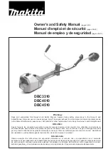
background image

4. 

(A)

 On the front face of the top beam, measure and mark 51.5in (130.8cm) from the center on 

each side. Draw a straight line with the speed square. 

(B)

 Position a 

stud mount

 on the outside of each 51.5in line, with the shorter angle of the stud 

mounts toward the top. On one side, push the bottom of the mount against the bottom of the top 

beam, use a speed square as a guide to keep it on the 51.5in line, and screw it into the top beam 

with four 

short wood screws

. The bottom of the mount should be as flush as possible with the 

bottom of the top beam and exactly perpendicular to the beam. Repeat on the other side. Use 

the above Drew’s Note for mounting tips!
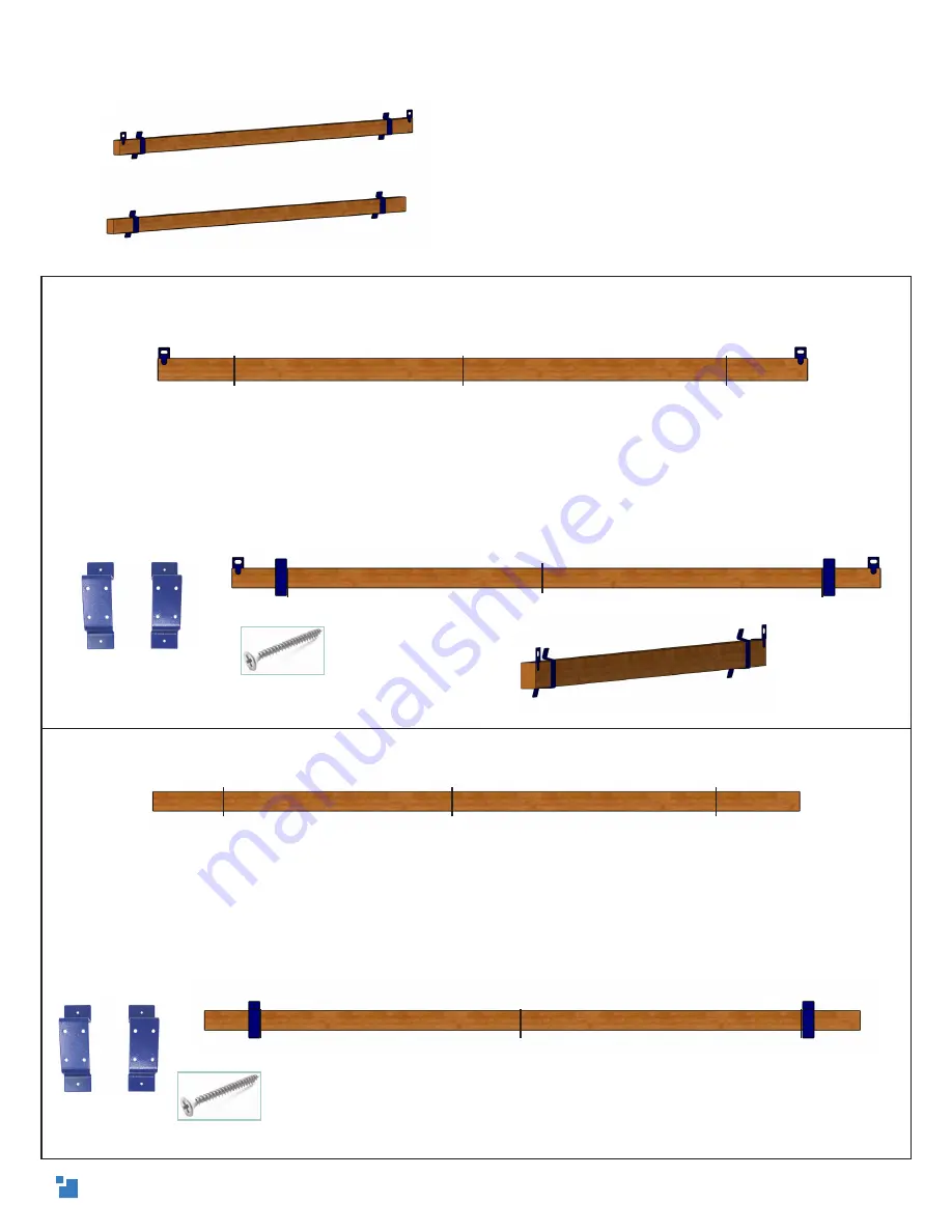
5. 

(A)

 On the front 4in face of the bottom beam, measure and mark 51.5in (130.8cm) from the 

center on each side. Draw a straight line with the speed square.

(B)

 Exactly like attaching to the top beam, position a 

stud mount 

on the outside of each 51.5in 

line, with the shorter angle of the stud mounts toward the top. On one side, push the bottom of 

the mount against the bottom of the top beam, use a speed square as a guide to keep it on the 

51.5in line, and screw it into the top beam with four 

short wood screws

. The bottom of the mount 

should be as flush as possible with the bottom of the top beam and exactly perpendicular to the 

beam. Repeat on the other side.

Attaching the stud mounts

Drew’s Note:  For the M2’s alignment calibration 
calculation (that’s fun to say), we have to 
make sure that the stud mounts are exactly 
perpendicular to the beams. To ensure this, 
attach each screw part-way before moving 
to the next. Repeat on the other two holes and 
screw in each from opposite sides by small 
increments until they are all tight - just like 
changing a tire.

1.5in short wood screw

center

51.5in

51.5in

center

51.5in

51.5in

center

51.5in

51.5in

center

51.5in

51.5in

1.5in short wood screw

stud mount

Side view

stud mount

7

Summary of Contents for M2 CNC

Page 1: ...v 1 5 Updated 8 30 21 Maker Made LLC The Standard Frame A guide to assembling the recommended 10ft top beam frame for our MakerMade M2 CNC Kit Set Up Guide for...

Page 2: ...ching the motors 6 Attaching the stud mounts 7 Frame legs 8 Attaching the canvas frame 10 Leveling your frame 11 Optional skirts 12 Attaching the chains 13 Mounting the M2 to your frame 14 Arduino DUE...

Page 3: ...font and look like this Drew s Note Let us know how this guide can be improved We love to hear from you Drew s notes are meant to answer some of the why questions you might have and give you tips to...

Page 4: ...lso work Canvas Wasteboards 1 a second one is optional 1in x 6in x 8ft Bottom Skirt and optional top skirt see Part 6 2 optional 1in x 6in x 4ft Side Skirts Cut a 1in x 6in x 8ft in two if not availab...

Page 5: ...gs with another canvas wasteboard D On the 37in line position another canvas wasteboard with the speed square and use a 2in x 4in board to support the top edge of the waste board while aligning and at...

Page 6: ...ne short wood screw in the front and two in diagonal holes in the top C Place one X Y motor in each bracket with the black cylindrical ends toward the center Use the motor washers between the bracket...

Page 7: ...to the top beam position a stud mount on the outside of each 51 5in line with the shorter angle of the stud mounts toward the top On one side push the bottom of the mount against the bottom of the top...

Page 8: ...aw another perpendicular line intersecting the 70in and 76 75in lines Repeat on the other leg 7 Arrange the vertical frame legs parallel on the floor resting on their 2in edges Position the bottom bea...

Page 9: ...horizontal frame legs write back on the ends of the 2in x 4in x 3ft boards Align the back end on the inside of the vertical frame legs at a 90 degree angle to make an L shape Use the speed square to e...

Page 10: ...beam Attach to the canvases to the horizontal frame legs with two long wood screws on each side C Attach the top of the canvases to the bottom beam using three evenly spaced short wood screws on each...

Page 11: ...is level This is especially useful in locations that don t have level floors Front Leveling your frame Drew s Note It s very important that your frame is square and level All of the M2 calibrations ar...

Page 12: ...he side skirts measure and mark 1 5in 3 8cm in on each side of the canvases closest to the stud mounts Attach a 4ft side skirt to each side using 4 short wood screws Attaching the skirts Drew s Note A...

Page 13: ...tighten the link On the left side attach the spring and tighten the quick link ensuring the link nut is facing away from the beam D Carefully stretch out the spring from the left side to attach it to...

Page 14: ...chain thread through the opposite roller bearing carriage and attach with the other cotter pin into the second to last chain link Let go of the sled and it will rest against the canvas Drew s Note We...

Page 15: ...ocontroller We recommend mounting the DUE to the wall behind your frame but it can be mounted in any safe location where it won t be stepped on or in conflict with the M2 during operation ARDUINO DUE...

Page 16: ...r machine Use adequate dust collection or wear a respirator Breathing material dust can be harmful Use proper lifting techniques when loading unloading materials Always use caution when connecting rem...

Page 17: ...Motor Mounting Brackets 2 Stud Mounts 4 Ring Carriage Roller Bearing Carriages 2 Z Axis Mount L Brackets 3 Z Axis Assembly Sled Router Clamp Roller Bearings 4 Chains 335cm 11ft 2 Dust Collection Brac...

Page 18: ...nger silver wood screws X Y Motor Hardware Bag E Motor sprocket 2 Grub Screws 2 Motor screws 8 Motor washers 8 Bearing Carriage Hardware Bag F Shoulder bolt 4 Large washer 8 Large locking nut 4 Ring a...

Page 19: ...wide 8ft 2 4m tall 8 5ft 2 6m long APPENDIX 3 OVERALL DIMENSIONS It s 6 5ft 1 98m from the floor to the top of the x y motors If the 8ft vertical frame legs are cut down optional 10ft 3 05m long at th...

Page 20: ...s to maintain a 15 degree angle 3 The target distance of the motor offset from where the chain leaves the motor sprockets to the top of the wasteboard should be at least 18 for a 10ft top beam 24 for...

Reviews: