background image


Installation-Mounting 


Mounting  kit  supplied  as  standard  along  with  the  turnstiles 
consists  of  studs  and  washers  Follow  the  procedure  below  for 
installation: 


Mark the hole places on the ground in which the turnstile will 
be mounted.  


Drill 8 cm deeped marked mounting holes by 12mm drill top 
as using drill and hilt.


Fix the steel anchors to the drilled holes. If the ground is not 
strong, fix the steel anchors using chemical soil mixture 
(recommended one is Hilti HIT HY 150). Wait 20 minutes for 
hardening of chemical soil mixture. 


Concrete thickness should be at least '400 mm'. 


Concrete edge dimensions should be at least '100 mm' longer than the turnstile dimension. 

Summary of Contents for T2500D SINGLE 3

Page 1: ...LLHEIGHT TURNSTILE USER MANUAL T2500D SINGLE 3 ARMED T2500D SINGLE 4 ARMED T2500D DOUBLE 3 ARMED T2500D DOUBLE 4 ARMED T2500K SINGLE 3 ARMED T2500K SINGLE 4 ARMED T2500K DOUBLE 3 ARMED T2500K DOUBLE 4...

Page 2: ...Contents Attention Technical Specificitaion Physical Specifications Installation and Mounting Connections Maintenance Instruction Documents 3 3 4 6 7 8 9...

Page 3: ...ater directly on the turnstile Contact your authorized service center for turnstile maintenance and repair Products must be in their original packaging when transported Pay attention to the instructio...

Page 4: ...Physical Specification Dimensions are given in mm 4 T2500D SINGLE 3 ARMED T2500D DOUBLE 3 ARMED T2500D DOUBLE 4 ARMED T2500D SINGLE 4 ARMED...

Page 5: ...Dimensions are given in mm 5 T2500K SINGLE 3 ARMED T2500K SINGLE 4 ARMED T2500K DOUBLE 3 ARMED T2500K DOUBLE 4 ARMED...

Page 6: ...Drill 8 cm deeped marked mounting holes by 12mm drill top as using drill and hilt Fix the steel anchors to the drilled holes If the ground is not strong fix the steel anchors using chemical soil mixt...

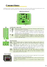
Page 7: ...pressing the MODE button the card will switch to LOCKED CONTROLLED FREE modes each time this switch is touched After selecting the desired mode press MODE SW 3 again LED 5 is off The tourniquet is th...

Page 8: ...ol Equipments and Rotation Parts The mechanism is rotated one turn to see if it is working properly rotating parts Central Control Element Tubes and working surfaces The problematic parts are checked...

Page 9: ...Documents 9...

Reviews: