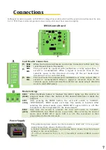
Card Reader Connection
J5
SER+
SER-
When the button and remote control are connected to this port, the
turnstile switches to free mode.
J5
GIR+
GIR-
This port must be operated with pushbutton or relay output. Max. 1
second is recommended. When a signal is received from J5, the
turnstile opens in the direction of entry. (If the set mode input
direction is set to controlled pass).
J5
CIK+
CIK-
This port must be operated with pushbutton or relay output. Max. 1
second is recommended. When a signal is received from J5, the
turnstile opens in the exit direction. (If the set mode output direction
is set to controlled pass).
Mode Settings
SW-3
(MODE)
When the Mode button is touched, the LED 5 lights up. The card is in
program mode. Press the button of the desired direction to make the
program.
SW-1
(GİRİŞ)
After pressing the MODE button, the card will switch to 'LOCKED',
'CONTROLLED', 'FREE' modes each time this switch is touched. After
selecting the desired mode, press MODE SW-3 again. LED 5 is off. The
tourniquet is then programmed to the desired mode.
SW-2
(ÇIKIŞ)
Each time the switch is pressed, the card will switch to 'LOCKED',
'CONTROLLED', and 'FREE' modes, respectively. After selecting the desired
mode, press MODE SW-3 again. LED 5 is off. The tourniquet is then
programmed to the desired mode.
The preferred power source for the turnstile is 25W, 24V, 1.1A. A power
supply below these values should not be used.
L N Port: 220AC V is applied. A grounding line is drawn from the ground
symbol to the turnstile body.
-V +V Port: Connect to V+(+) to V- (-) towards J1 socket of BM32 control
board.
Fullheight turnstiles operate with 220VAC voltage. Power cable which will be used in turnstiles must be min.
3 x 1.5 TTR. Power cable and ground connections points must be screwed in tightly.
BM32 Control Board
Power Supply
Connections
7
Summary of Contents for T2500D SINGLE 3
Page 9: ...Documents 9...


