4V2A1563 (E)
6 - 1
6.1
Overview
This chapter contains information on maintaining the Makino V55 14,000
and 20,000 rpm, (11A Type) spindle heads, at peak operation.
Descriptions of the design, principle of operations, and procedures for
maintenance and adjustment of the spindle’s main assemblies, and
peripheral components are provided.
The X and Z axes provide all spindle movement. The spindle assembly is
contained within the ram casting. The ram casting travels vertically form-
ing the Z axis and is mounted to the front of the saddle. The saddle is
mounted on top of the column forming the X axis.
6.2
Spindle Design
Spindle rotation from 15 to 14,000 (or 200 to 20,000) rpm, programmable
in 1 rpm increments, is provided by an integral AC servo motor consisting
of a stator housed in the spindle cartridge and a rotor on the spindle shaft.
Spindle rotation is monitored by a pulse coder ring/sensor assembly
located at the rear of the spindle shaft. A Fanuc digital spindle drive sys-
tem controls rotation, orientation, and rigid tapping.
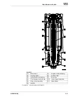
The spindle is supported by two pre-loaded angular contact ball bearings
at the nose and one single row roller bearing, at the top. This bearing
arrangement provides maximum spindle rigidity and accuracy, by absorb-
ing axial and radial cutting forces. The bearing pre-load is set at the fac-
tory.
•
Spindle Nose Taper: 7/24 ISO #40 taper.
Tooling is securely retained in the spindle taper by the draw bar assembly,
housed inside the spindle. The draw bar assembly consists of the draw
bar, disc (Belleville) springs, and the collet finger assembly.
•
Tool Clamping Force: 1980kg (4366lb)
The draw bar is a “positive mechanical” clamping mechanism and is “nor-
mally” clamped. Tooling is released when the spindle is unclamped, by
hydraulically advancing the draw bar assembly.
Summary of Contents for V55
Page 6: ...vi...
Page 32: ...1 24 NOTES SKETCHES...
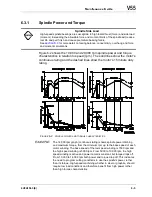
Page 37: ...4V2A1563 E 2 3 FIGURE 2 1 SPINDLE POWER AND TORQUE CHARACTERISTICS...
Page 39: ...4V2A1563 E 2 5 FIGURE 2 2 AXIS CONFIGURATION TRAVEL AND WORK CUBE...
Page 41: ...4V2A1563 E 2 7 FIGURE 2 4 WORKPIECE SIZE LIMITATIONS...
Page 53: ...4V2A1563 E 2 19 FIGURE 2 6 FLOOR SPACE FOR STANDARD MACHINE...
Page 58: ...2 24 F IGURE 2 7 V55 WITH 25 TOOL ATC...
Page 59: ...4V2A1563 E 2 25 F IGURE 2 8 V55 WITH 25 TOOL ATC AND LIFT UP CHIP CONVEYOR LEFT...
Page 60: ...2 26 F IGURE 2 9 V55 WITH 25 TOOL ATC AND LIFT UP CHIP CONVEYOR RIGHT...
Page 61: ...4V2A1563 E 2 27 F IGURE 2 10 V55 WITH 25 TOOL ATC LIFT UP CHIP CONVEYOR LEFT AND APC...
Page 62: ...2 28 F IGURE 2 11 V55 WITH 25 TOOL ATC LIFT UP CHIP CONVEYOR RIGHT AND APC...
Page 63: ...4V2A1563 E 2 29 F IGURE 2 12 V55 WITH 40 OR 80 TOOL ATC...
Page 64: ...2 30 F IGURE 2 13 V55 WITH 40 OR 80 TOOL ATC AND LIFT UP CHIP CONVEYOR LEFT...
Page 65: ...4V2A1563 E 2 31 F IGURE 2 14 V55 WITH 40 OR 80 TOOL ATC AND LIFT UP CHIP CONVEYOR RIGHT...
Page 66: ...2 32 F IGURE 2 15 V55 WITH 40 OR 80 TOOL ATC LIFT UP CHIP CONVEYOR LEFT AND APC...
Page 67: ...4V2A1563 E 2 33 F IGURE 2 16 V55 WITH 40 OR 80 TOOL ATC LIFT UP CHIP CONVEYOR RIGHT AND APC...
Page 68: ...2 34 NOTES SKETCHES...
Page 93: ...4V2A1563 E 3 23 FIGURE 3 6 LEVELING BASE POSITIONS AND BED TO FLOOR CLEARANCE...
Page 94: ...3 24 NOTES SKETCHES...
Page 99: ...4V2A1563 E 4 3 FIGURE 4 1 MACHINE CORE ELEMENTS...
Page 103: ...4V2A1563 E 4 7 FIGURE 4 3 MAKINO PROFESSIONAL 3 CONTROL WITH MPC5...
Page 106: ...4 10 NOTES SKETCHES...
Page 114: ...4 18 NOTES SKETCHES...
Page 123: ...4V2A1563 E 5 5 FIGURE 5 1 BASIC TROUBLESHOOTING FLOW CHART...
Page 124: ...5 6 NOTES SKETCHES...
Page 143: ...4V2A1563 E 5 25 NOTES SKETCHES...
Page 153: ...4V2A1563 E 5 35 NOTES SKETCHES...
Page 159: ...4V2A1563 E 5 41 NOTES SKETCHES...
Page 166: ...5 48 NOTES SKETCHES...
Page 191: ...4V2A1563 E 5 73 TEC F IGURE 5 26 S CHEMATIC PAGE FORMAT...
Page 197: ...4V2A1563 E 5 79 NOTES SKETCHES...
Page 198: ...5 80 NOTES SKETCHES...
Page 202: ...NOTES SKETCHES...
Page 227: ...4V2A1563 E 6 25 NOTES SKETCHES...
Page 252: ...6 50 NOTES SKETCHES...
Page 261: ...4V2A1563 E 6 59 FIGURE 6 36 SPINDLE HYDRAULIC CIRCUIT...
Page 267: ...4V2A1563 E 6 65 FIGURE 6 40 L PORT SPINDLE LUBRICATION...
Page 269: ...4V2A1563 E 6 67 FIGURE 6 41 V PORT SPINDLE LUBRICATION...
Page 277: ...4V2A1563 E 6 75 NOTES SKETCHES...
Page 279: ...4V2A1563 E 6 77 FIGURE 6 48 SEALING ROD INSTALLATION...
Page 284: ...6 82 NOTES SKETCHES...
Page 293: ...4V2A1563 E 7 5 F IGURE 7 3 AXIS DRIVE CIRCUIT...
Page 297: ...4V2A1563 E 7 9 NOTES SKETCHES...
Page 309: ...4V2A1563 E 7 21 FIGURE 7 12 BALL SCREW COOLING OIL AND TAC BEARING LUBRICATION PIPING...
Page 311: ...4V2A1563 E 7 23 NOTES SKETCHES...
Page 317: ...4V2A1563 E 7 29 FIGURE 7 18 BALL SCREW PRE TENSION PROCEDURE...
Page 346: ...7 58 NOTES SKETCHES...
Page 348: ...7 60 FIGURE 7 35 Y AXIS COVER SYSTEM...
Page 351: ...4V2A1563 E 7 63 NOTES SKETCHES...
Page 369: ...4V2A1563 E 7 81 NOTES SKETCHES...
Page 370: ...7 82 NOTES SKETCHES...
Page 374: ...NOTES SKETCHES...
Page 386: ...8 12 NOTES SKETCHES...
Page 403: ...4V2A1563 E 8 29 NOTES SKETCHES...
Page 423: ...4V2A1563 E 8 49 NOTES SKETCHES...
Page 432: ...8 58 NOTES SKETCHES...
Page 439: ...4V2A1563 E 9 5 NOTES SKETCHES...
Page 441: ...4V2A1563 E 9 7 F IGURE 9 3 OIL CONTROLLER ELECTRICAL DRAWINGS...
Page 443: ...4V2A1563 E 9 9 FIGURE 9 4 OIL CONTROLLER MACHINE SYSTEM...
Page 464: ...9 30 NOTES SKETCHES...
Page 468: ...NOTES SKETCHES...
Page 490: ...A 22 NOTES SKETCHES...
Page 525: ...4V2A1563 E A 57 NOTES SKETCHES...
Page 526: ...A 58 NOTES SKETCHES...
Page 534: ...B 6 NOTES SKETCHES...
Page 546: ...B 18 NOTES SKETCHES...
Page 558: ...B 30 NOTES SKETCHES...
Page 564: ...B 36 NOTES SKETCHES...
Page 568: ...B 40 NOTES SKETCHES...

