7 - 52
7.9
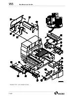
Axis Covers and Chip Scraper Unit
The machine is equipped with numerous sheet metal covers enclosing the
machining area to contain coolant, chips, and machine surfaces. A major-
ity of the covers are stationary and do not require removal for mainte-
nance procedures. This section discusses the X axis Roll-up, Y axis guide
way, and ball screw covers which may require removal.
7.9.1
X Axis Roll-up Cover
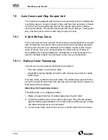
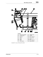
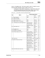
The X axis roll-up cover consists of two roll-up cover assemblies (on each
side of machine) mounted to frame work above the machining area with
the free end of each cover attached to the saddle. As the X axis moves
(plus or minus) one cover extends while the other rolls up. Roll-up is
accomplished by spring loading the mechanism. A tensioning device is
used to maintain proper cover tension on the roll-up mechanisms.
7.9.1.1
Roll-up Cover Tensioning
The roll-up cover tensioning mechanism consists of:
•
Two wire cables, one for each roller
•
Adjustable, spring loaded, tensioner with cleaves type ends for cable
attachment
One wire cable is attached to each roller. The cables wrap several times
around one end of each roller with the free ends connected by cleaves on
both ends of the tensioner.
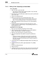
Attaching the Tensioning Cables:
If installing new or re-wrapping cables:
1. Make an equal number of cable wraps around each roller.
2. Check the position where the cable ends meet. They should extend
approximately equal distances from each roller and far enough to allow
the tensioning device to be connected.
3. Connect the cable ends to the cleaves on both ends of the tensioner.
Summary of Contents for V55
Page 6: ...vi...
Page 32: ...1 24 NOTES SKETCHES...
Page 37: ...4V2A1563 E 2 3 FIGURE 2 1 SPINDLE POWER AND TORQUE CHARACTERISTICS...
Page 39: ...4V2A1563 E 2 5 FIGURE 2 2 AXIS CONFIGURATION TRAVEL AND WORK CUBE...
Page 41: ...4V2A1563 E 2 7 FIGURE 2 4 WORKPIECE SIZE LIMITATIONS...
Page 53: ...4V2A1563 E 2 19 FIGURE 2 6 FLOOR SPACE FOR STANDARD MACHINE...
Page 58: ...2 24 F IGURE 2 7 V55 WITH 25 TOOL ATC...
Page 59: ...4V2A1563 E 2 25 F IGURE 2 8 V55 WITH 25 TOOL ATC AND LIFT UP CHIP CONVEYOR LEFT...
Page 60: ...2 26 F IGURE 2 9 V55 WITH 25 TOOL ATC AND LIFT UP CHIP CONVEYOR RIGHT...
Page 61: ...4V2A1563 E 2 27 F IGURE 2 10 V55 WITH 25 TOOL ATC LIFT UP CHIP CONVEYOR LEFT AND APC...
Page 62: ...2 28 F IGURE 2 11 V55 WITH 25 TOOL ATC LIFT UP CHIP CONVEYOR RIGHT AND APC...
Page 63: ...4V2A1563 E 2 29 F IGURE 2 12 V55 WITH 40 OR 80 TOOL ATC...
Page 64: ...2 30 F IGURE 2 13 V55 WITH 40 OR 80 TOOL ATC AND LIFT UP CHIP CONVEYOR LEFT...
Page 65: ...4V2A1563 E 2 31 F IGURE 2 14 V55 WITH 40 OR 80 TOOL ATC AND LIFT UP CHIP CONVEYOR RIGHT...
Page 66: ...2 32 F IGURE 2 15 V55 WITH 40 OR 80 TOOL ATC LIFT UP CHIP CONVEYOR LEFT AND APC...
Page 67: ...4V2A1563 E 2 33 F IGURE 2 16 V55 WITH 40 OR 80 TOOL ATC LIFT UP CHIP CONVEYOR RIGHT AND APC...
Page 68: ...2 34 NOTES SKETCHES...
Page 93: ...4V2A1563 E 3 23 FIGURE 3 6 LEVELING BASE POSITIONS AND BED TO FLOOR CLEARANCE...
Page 94: ...3 24 NOTES SKETCHES...
Page 99: ...4V2A1563 E 4 3 FIGURE 4 1 MACHINE CORE ELEMENTS...
Page 103: ...4V2A1563 E 4 7 FIGURE 4 3 MAKINO PROFESSIONAL 3 CONTROL WITH MPC5...
Page 106: ...4 10 NOTES SKETCHES...
Page 114: ...4 18 NOTES SKETCHES...
Page 123: ...4V2A1563 E 5 5 FIGURE 5 1 BASIC TROUBLESHOOTING FLOW CHART...
Page 124: ...5 6 NOTES SKETCHES...
Page 143: ...4V2A1563 E 5 25 NOTES SKETCHES...
Page 153: ...4V2A1563 E 5 35 NOTES SKETCHES...
Page 159: ...4V2A1563 E 5 41 NOTES SKETCHES...
Page 166: ...5 48 NOTES SKETCHES...
Page 191: ...4V2A1563 E 5 73 TEC F IGURE 5 26 S CHEMATIC PAGE FORMAT...
Page 197: ...4V2A1563 E 5 79 NOTES SKETCHES...
Page 198: ...5 80 NOTES SKETCHES...
Page 202: ...NOTES SKETCHES...
Page 227: ...4V2A1563 E 6 25 NOTES SKETCHES...
Page 252: ...6 50 NOTES SKETCHES...
Page 261: ...4V2A1563 E 6 59 FIGURE 6 36 SPINDLE HYDRAULIC CIRCUIT...
Page 267: ...4V2A1563 E 6 65 FIGURE 6 40 L PORT SPINDLE LUBRICATION...
Page 269: ...4V2A1563 E 6 67 FIGURE 6 41 V PORT SPINDLE LUBRICATION...
Page 277: ...4V2A1563 E 6 75 NOTES SKETCHES...
Page 279: ...4V2A1563 E 6 77 FIGURE 6 48 SEALING ROD INSTALLATION...
Page 284: ...6 82 NOTES SKETCHES...
Page 293: ...4V2A1563 E 7 5 F IGURE 7 3 AXIS DRIVE CIRCUIT...
Page 297: ...4V2A1563 E 7 9 NOTES SKETCHES...
Page 309: ...4V2A1563 E 7 21 FIGURE 7 12 BALL SCREW COOLING OIL AND TAC BEARING LUBRICATION PIPING...
Page 311: ...4V2A1563 E 7 23 NOTES SKETCHES...
Page 317: ...4V2A1563 E 7 29 FIGURE 7 18 BALL SCREW PRE TENSION PROCEDURE...
Page 346: ...7 58 NOTES SKETCHES...
Page 348: ...7 60 FIGURE 7 35 Y AXIS COVER SYSTEM...
Page 351: ...4V2A1563 E 7 63 NOTES SKETCHES...
Page 369: ...4V2A1563 E 7 81 NOTES SKETCHES...
Page 370: ...7 82 NOTES SKETCHES...
Page 374: ...NOTES SKETCHES...
Page 386: ...8 12 NOTES SKETCHES...
Page 403: ...4V2A1563 E 8 29 NOTES SKETCHES...
Page 423: ...4V2A1563 E 8 49 NOTES SKETCHES...
Page 432: ...8 58 NOTES SKETCHES...
Page 439: ...4V2A1563 E 9 5 NOTES SKETCHES...
Page 441: ...4V2A1563 E 9 7 F IGURE 9 3 OIL CONTROLLER ELECTRICAL DRAWINGS...
Page 443: ...4V2A1563 E 9 9 FIGURE 9 4 OIL CONTROLLER MACHINE SYSTEM...
Page 464: ...9 30 NOTES SKETCHES...
Page 468: ...NOTES SKETCHES...
Page 490: ...A 22 NOTES SKETCHES...
Page 525: ...4V2A1563 E A 57 NOTES SKETCHES...
Page 526: ...A 58 NOTES SKETCHES...
Page 534: ...B 6 NOTES SKETCHES...
Page 546: ...B 18 NOTES SKETCHES...
Page 558: ...B 30 NOTES SKETCHES...
Page 564: ...B 36 NOTES SKETCHES...
Page 568: ...B 40 NOTES SKETCHES...


