


7 - 76
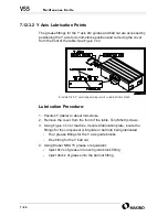
7.11
Setting CNC Parameters
Certain maintenance functions require setting or adjusting related CNC
parameters to restore the machine to original operating condition. The fol-
lowing procedure provides the basic steps to set CNC parameters. Setting
values differ depending the parameter number. Refer CNC Maintenance
Manual details related to specific parameter setting values.
The parameters subject to setting or adjustment include:
•
1850 Grid Shift, see
•
1851 and 1852 Backlash, see
The control provides the capability to “password” protect the CNC param-
eters. If active, the password must be known in order to activate the
Parameter Write Enable function.
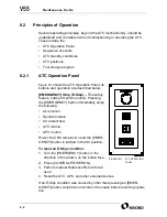
1. Activate PWE (Parameter Write Enable) to unlock CNC parameters.
A. Select MDI mode.
B. Press the [OFFSET SETTING] function key.
C. Press the [SETING] softkey, to select the
(SETTING HANDY)
screen.
D. Select the
PARAMETER WRITE
field.
E. Key-in a ’1’ and press
[INPUT]
.
2. Press the [SYSTEM] function key.
3. Key-in the required parameter number press the
[NO. SRCH] softkey.
4. If the parameter has separate fields for the X, Y, and Z axes. Use the
cursor
keys to highlight the field to be set.
5. Key-in the parameter setting value and press the [INPUT] key.
6. Deactivate PWE, locking the parameters.
A. Press the [OFFSET SETTING] function key.
B. Press the [SETING] softkey, to select the
(SETTING HANDY)
screen.
C. Select the
PARAMETER WRITE
field.
D. Key-in a ’0’ and press
[INPUT]
.
E. Press the
[RESET]
key, to clear the alarm.
F. Press the
[CONTROL POWER OFF]
button, to turn the control Off.
These CNC parameters require the control be turned Off then back On,
before the parameter change takes effect.
Summary of Contents for V55
Page 6: ...vi...
Page 32: ...1 24 NOTES SKETCHES...
Page 37: ...4V2A1563 E 2 3 FIGURE 2 1 SPINDLE POWER AND TORQUE CHARACTERISTICS...
Page 39: ...4V2A1563 E 2 5 FIGURE 2 2 AXIS CONFIGURATION TRAVEL AND WORK CUBE...
Page 41: ...4V2A1563 E 2 7 FIGURE 2 4 WORKPIECE SIZE LIMITATIONS...
Page 53: ...4V2A1563 E 2 19 FIGURE 2 6 FLOOR SPACE FOR STANDARD MACHINE...
Page 58: ...2 24 F IGURE 2 7 V55 WITH 25 TOOL ATC...
Page 59: ...4V2A1563 E 2 25 F IGURE 2 8 V55 WITH 25 TOOL ATC AND LIFT UP CHIP CONVEYOR LEFT...
Page 60: ...2 26 F IGURE 2 9 V55 WITH 25 TOOL ATC AND LIFT UP CHIP CONVEYOR RIGHT...
Page 61: ...4V2A1563 E 2 27 F IGURE 2 10 V55 WITH 25 TOOL ATC LIFT UP CHIP CONVEYOR LEFT AND APC...
Page 62: ...2 28 F IGURE 2 11 V55 WITH 25 TOOL ATC LIFT UP CHIP CONVEYOR RIGHT AND APC...
Page 63: ...4V2A1563 E 2 29 F IGURE 2 12 V55 WITH 40 OR 80 TOOL ATC...
Page 64: ...2 30 F IGURE 2 13 V55 WITH 40 OR 80 TOOL ATC AND LIFT UP CHIP CONVEYOR LEFT...
Page 65: ...4V2A1563 E 2 31 F IGURE 2 14 V55 WITH 40 OR 80 TOOL ATC AND LIFT UP CHIP CONVEYOR RIGHT...
Page 66: ...2 32 F IGURE 2 15 V55 WITH 40 OR 80 TOOL ATC LIFT UP CHIP CONVEYOR LEFT AND APC...
Page 67: ...4V2A1563 E 2 33 F IGURE 2 16 V55 WITH 40 OR 80 TOOL ATC LIFT UP CHIP CONVEYOR RIGHT AND APC...
Page 68: ...2 34 NOTES SKETCHES...
Page 93: ...4V2A1563 E 3 23 FIGURE 3 6 LEVELING BASE POSITIONS AND BED TO FLOOR CLEARANCE...
Page 94: ...3 24 NOTES SKETCHES...
Page 99: ...4V2A1563 E 4 3 FIGURE 4 1 MACHINE CORE ELEMENTS...
Page 103: ...4V2A1563 E 4 7 FIGURE 4 3 MAKINO PROFESSIONAL 3 CONTROL WITH MPC5...
Page 106: ...4 10 NOTES SKETCHES...
Page 114: ...4 18 NOTES SKETCHES...
Page 123: ...4V2A1563 E 5 5 FIGURE 5 1 BASIC TROUBLESHOOTING FLOW CHART...
Page 124: ...5 6 NOTES SKETCHES...
Page 143: ...4V2A1563 E 5 25 NOTES SKETCHES...
Page 153: ...4V2A1563 E 5 35 NOTES SKETCHES...
Page 159: ...4V2A1563 E 5 41 NOTES SKETCHES...
Page 166: ...5 48 NOTES SKETCHES...
Page 191: ...4V2A1563 E 5 73 TEC F IGURE 5 26 S CHEMATIC PAGE FORMAT...
Page 197: ...4V2A1563 E 5 79 NOTES SKETCHES...
Page 198: ...5 80 NOTES SKETCHES...
Page 202: ...NOTES SKETCHES...
Page 227: ...4V2A1563 E 6 25 NOTES SKETCHES...
Page 252: ...6 50 NOTES SKETCHES...
Page 261: ...4V2A1563 E 6 59 FIGURE 6 36 SPINDLE HYDRAULIC CIRCUIT...
Page 267: ...4V2A1563 E 6 65 FIGURE 6 40 L PORT SPINDLE LUBRICATION...
Page 269: ...4V2A1563 E 6 67 FIGURE 6 41 V PORT SPINDLE LUBRICATION...
Page 277: ...4V2A1563 E 6 75 NOTES SKETCHES...
Page 279: ...4V2A1563 E 6 77 FIGURE 6 48 SEALING ROD INSTALLATION...
Page 284: ...6 82 NOTES SKETCHES...
Page 293: ...4V2A1563 E 7 5 F IGURE 7 3 AXIS DRIVE CIRCUIT...
Page 297: ...4V2A1563 E 7 9 NOTES SKETCHES...
Page 309: ...4V2A1563 E 7 21 FIGURE 7 12 BALL SCREW COOLING OIL AND TAC BEARING LUBRICATION PIPING...
Page 311: ...4V2A1563 E 7 23 NOTES SKETCHES...
Page 317: ...4V2A1563 E 7 29 FIGURE 7 18 BALL SCREW PRE TENSION PROCEDURE...
Page 346: ...7 58 NOTES SKETCHES...
Page 348: ...7 60 FIGURE 7 35 Y AXIS COVER SYSTEM...
Page 351: ...4V2A1563 E 7 63 NOTES SKETCHES...
Page 369: ...4V2A1563 E 7 81 NOTES SKETCHES...
Page 370: ...7 82 NOTES SKETCHES...
Page 374: ...NOTES SKETCHES...
Page 386: ...8 12 NOTES SKETCHES...
Page 403: ...4V2A1563 E 8 29 NOTES SKETCHES...
Page 423: ...4V2A1563 E 8 49 NOTES SKETCHES...
Page 432: ...8 58 NOTES SKETCHES...
Page 439: ...4V2A1563 E 9 5 NOTES SKETCHES...
Page 441: ...4V2A1563 E 9 7 F IGURE 9 3 OIL CONTROLLER ELECTRICAL DRAWINGS...
Page 443: ...4V2A1563 E 9 9 FIGURE 9 4 OIL CONTROLLER MACHINE SYSTEM...
Page 464: ...9 30 NOTES SKETCHES...
Page 468: ...NOTES SKETCHES...
Page 490: ...A 22 NOTES SKETCHES...
Page 525: ...4V2A1563 E A 57 NOTES SKETCHES...
Page 526: ...A 58 NOTES SKETCHES...
Page 534: ...B 6 NOTES SKETCHES...
Page 546: ...B 18 NOTES SKETCHES...
Page 558: ...B 30 NOTES SKETCHES...
Page 564: ...B 36 NOTES SKETCHES...
Page 568: ...B 40 NOTES SKETCHES...


