11 ENGLISH
Switch action
CAUTION:
Before installing the battery cartridge
into the tool, always check to see that the slide switch
moves properly and returns to the "OFF" position
when the rear of the slide switch is depressed.
►
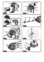
Fig.3:
1.
Slide switch
To start the tool, slide the slide switch toward the "I (ON)" position. For
continuous operation, press the front of the slide switch to lock it.
To stop the tool, press the rear of the slide switch, then
slide it toward the "O (OFF)" position.
Lighting up the front lamp
►
Fig.4:
1.
Lamp
CAUTION:
Do not look in the light or see the
source of light directly.
Turn on the switch to light up the lamp. The lamp keeps
on lighting while the switch is on. The lamp goes out
approximately 10 seconds after turning off the switch.
NOTE:
Use a dry cloth to wipe the dirt off the lens of
the lamp. Be careful not to scratch the lens of lamp, or
it may lower the illumination.
NOTE:
When the tool is overheated, the lamp blinks
for one minute. In this case, cool down the tool before
another operation.
Accidental re-start preventive function
Even if the battery cartridge is installed on the tool with the
slide switch in the "I (ON)" position, the tool does not start.
To start the tool, first slide the slide switch toward the "O
(OFF)" position and then slide it toward the "I (ON)" position.
Electronic function
The tool is equipped with the electronic functions for easy operation.
•
Soft start
The soft-start function minimizes start-up shock,
and makes the tool start smoothly.
ASSEMBLY
CAUTION:
Always be sure that the tool is
switched off and the battery cartridge is removed
before carrying out any work on the tool.
Installing or removing bit
NOTICE:
Do not tighten the collet nut without install-
ing a bit, or the collet cone may break.
►
Fig.5:
1.
Collet nut
2.
Shoe
3.
Shaft lock
4.
Tighten
5.
Loosen
Press the shaft lock to prevent shaft rotation when
installing or removing the bit.
To install the bit, insert it into the collet cone as far as
it goes and then tighten the collet nut securely with the
wrench or the shoe as a wrench.
To remove the bit, follow the installation procedure in reverse.
Changing the collet cone
Country specific
NOTICE:
Use the correct size collet cone for the bit
that you are going to use.
NOTICE:
Do not tighten the collet nut without install-
ing a bit, or the collet cone may break.
►
Fig.6:
1.
Collet cone
2.
Bit
3.
Collet nut
To change the collet cone, loosen the collet nut and
remove. Replace the installed collet cone with desired
collet cone. Reinstall collet nut.
Installing the shoe
To install the shoe, loosen the thumb screw first. Attach
the shoe on the tool, and then fix it firmly with the thumb
screw.
►
Fig.7:
1.
Shoe
2.
Thumb screw
Hook
CAUTION:
Never hook the tool at high loca-
tion or on potentially unstable surface.
►
Fig.8:
1.
Groove
2.
Hook
3.
Screw
The hook is convenient for temporarily hanging the tool.
To install the hook, insert it into a groove in the tool
housing and then secure it with a screw. To remove,
loosen the screw and then take it out.
Strap hole
The strap hole is provided for hanging the tool on the
wall using a strap.
►
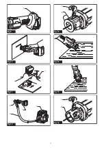
Fig.9:
1.
Strap hole
WARNING:
Do not use the strap hole for any
other purpose than hanging the tool on the wall.
Doing so may result serious injury because the strap
hole is not intended for any other purpose than hang-
ing the tool on the wall.
OPERATION
CAUTION:
Avoid forcing the bit to bend or twist.
It may snap.
CAUTION:
Before turning the tool on, make sure
the bit and collet nut are securely tightened.
CAUTION:
Always use the tool with a base such
as the shoe or the vacuum cover attached.
Hold the tool securely with the bit pointing in a safe
direction while it is not contacting any surface. Turn the
tool on and wait until the tool reaches full speed.
►
Fig.10
When using the drywall guide bit into a drywall, carefully
insert the bit straight until the shoe base contacts the
material fully.
Move the tool slowly with a constant pressure in a
clockwise direction to make a cut.
Summary of Contents for 0088381727976
Page 2: ...1 2 3 Fig 1 1 2 Fig 2 1 Fig 3 1 Fig 4 1 3 2 4 5 Fig 5 1 3 2 Fig 6 1 2 Fig 7 1 3 2 Fig 8 2 ...
Page 3: ...1 Fig 9 Fig 10 1 Fig 11 2 1 3 4 Fig 12 1 2 Fig 13 Fig 14 Fig 15 1 2 Fig 16 3 ...
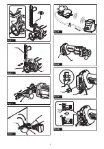
Page 5: ...1 Fig 25 1 2 1 2 Fig 26 Fig 27 1 Fig 28 1 2 Fig 29 1 Fig 30 5 ...
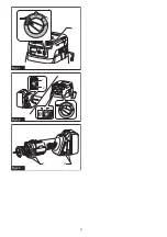
Page 6: ...1 Fig 31 1 2 1 2 Fig 32 1 2 Fig 33 6 ...
Page 91: ...91 ...


