12 ENGLISH
►
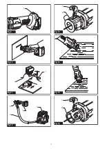
Fig.11:
1.
Guide board
When cutting a straight line, clamp a guide board firmly
to the material and use it as a guide. Move the tool in
the direction of the arrow with the shoe base flush with
the side of the guide board.
When the cut is complete, turn the tool off and wait for
the bit to stop rotating and then carefully pull it out from
the material.
NOTICE:
Do not apply exessive force to the bit
against the material.
Doing so may get the bit dull or
broken, or the tool out of order.
NOTE:
When cutting drywall around outlet box, cut in
a counterclockwise direction for ease of cut.
NOTE:
The standard bit included with this tool is for
cutting a drywall only. When cutting materials other
than drywall, do not use the standard drywall guide
bit.
Vacuum cover
To perform cleaner operations, use the vacuum cover
and connect the tool to Makita vacuum cleaner.
►
Fig.12:
1.
Tool
2.
Vacuum cover
3.
Hose
4.
Vacuum
cleaner
Loosen the thumb screw and remove the shoe. Attach
the vacuum cover, and fasten it securely with the thumb
screw.
►
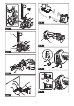
Fig.13:
1.
Thumb screw
2.
Vacuum cover
NOTE:
The circular guide (optional accessory) can be
installed on the vacuum cover.
Using multipurpose bit
Optional accessory
When using the multipurpose bit into the material, hold
the tool at approximately a 45 degree angle with the
edge of the shoe base contacting the material.
►
Fig.14
Bring the tool carefully to a straight position so the shoe
base contacts the material fully.
►
Fig.15
Circular guide
Optional accessory
Circular cutting diameters: 10 cm - 34 cm
Installing circular guide
Remove the thumb screw which secures the shoe.
►
Fig.16:
1.
Thumb screw
2.
Shoe
Align the projections in the circular guide with the
grooves in the shoe, and secure the shoe and circular
guide with the thumb screw.
►
Fig.17:
1.
Projections
2.
Shoe
To adjust the cutting depth, loosen the thumb screw
and then slide the shoe with the circular guide. After the
adjustment, tighten the thumb screw securely.
►
Fig.18:
1.
Thumb screw
2.
Circular guide
3.
Shoe
4.
Loosen
5.
Tighten
Using circular guide
Loosen the knob, and adjust its position in accordance
with the size of the circle to be cut. (The hole radius to
be cut are indicated on the side of the circular guide as
a general guideline.) After completion of the adjustment,
tighten the knob securely.
►
Fig.19:
1.
Knob
2.
Tighten
3.
Loosen
Place the tip of the knob into the center of the circle to
be cut, and proceed to cut in a clockwise direction.
►
Fig.20:
1.
Knob
WIRELESS ACTIVATION
FUNCTION
What you can do with the wireless
activation function
The wireless activation function enables clean and com
-
fortable operation. By connecting a supported vacuum
cleaner to the tool, you can run the vacuum cleaner
automatically along with the switch operation of the tool.
►
Fig.21
To use the wireless activation function, prepare follow-
ing items:
•
A wireless unit (optional accessory)
•
A vacuum cleaner which supports the wireless
activation function
The overview of the wireless activation function
setting is as follows. Refer to each section for detail
procedures.
1.
Installing the wireless unit
2.
Tool registration for the vacuum cleaner
3.
Starting the wireless activation function
Installing the wireless unit
Optional accessory
CAUTION:
Place the tool on a flat and stable
surface when installing the wireless unit.
NOTICE:
Clean the dust and dirt on the tool
before installing the wireless unit.
Dust or dirt
may cause malfunction if it comes into the slot of the
wireless unit.
NOTICE:
To prevent the malfunction caused by
static, touch a static discharging material, such
as a metal part of the tool, before picking up the
wireless unit.
NOTICE:
When installing the wireless unit,
always be sure that the wireless unit is inserted
in the correct direction and the lid is completely
closed.
Summary of Contents for 0088381727976
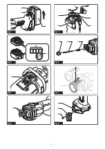
Page 2: ...1 2 3 Fig 1 1 2 Fig 2 1 Fig 3 1 Fig 4 1 3 2 4 5 Fig 5 1 3 2 Fig 6 1 2 Fig 7 1 3 2 Fig 8 2 ...
Page 3: ...1 Fig 9 Fig 10 1 Fig 11 2 1 3 4 Fig 12 1 2 Fig 13 Fig 14 Fig 15 1 2 Fig 16 3 ...
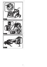
Page 5: ...1 Fig 25 1 2 1 2 Fig 26 Fig 27 1 Fig 28 1 2 Fig 29 1 Fig 30 5 ...
Page 6: ...1 Fig 31 1 2 1 2 Fig 32 1 2 Fig 33 6 ...
Page 91: ...91 ...


