background image

42 ENGLISH

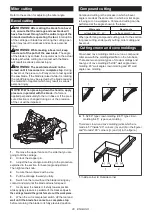
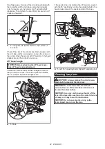
Carefully square the side of the circular saw blade with 

the top surface of the turn base using the triangular 

rule, try-square, etc. by turning the 0° adjusting bolt 

clockwise. Then tighten the knob firmly to secure the 0° 

angle you have set.

1

2

3

►    

1.

 Triangular rule 

2.

 Saw blade 

3.

 Top surface of 

turn base

Check if the side of the circular saw blade squares with 

the turn base surface once again. Loosen the screw on 

the pointer. Align the pointer with 0° position in the bevel 

angle scale and then tighten the screw.

45° bevel angle

NOTICE:


Before adjusting the 45° bevel angle, 

finish 0° bevel angle adjustment.

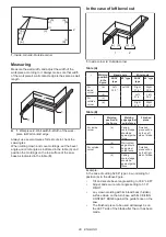
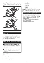
Loosen the knob and fully tilt the carriage to the side 

that you want to check. Check if the pointer indicates 

the 45° position in the bevel angle scale.

1

►    

1.

 Knob

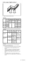
If the pointer does not indicate the 45° position, align it 

with the 45° position by turning the adjusting bolt in the 

bevel angle scale on the opposite side of the base.

1

2

►    

1.

 Left 45° adjusting bolt 

2.

 Right 45° adjusting bolt

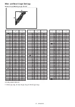
Cleaning lamp lens

CAUTION:


Always remove the circular saw 

blade before cleaning the lamp lens.

NOTICE:


Do not remove the screw which 

secures the lens. If the lens does not come out, 

loosen the screw further. 

NOTICE:


Use a dry cloth to wipe the dirt off the 

lens of the lamp. Be careful not to scratch the lens 

of lamp, or it may lower the illumination.

NOTICE:


Do not use solvents or any petro-

leum-based cleaners on the lens.

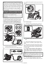
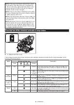
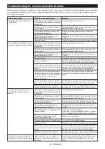
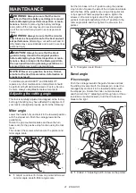
Summary of Contents for 088381-748520

Page 1: ...INSTRUCTION MANUAL MANUAL DE INSTRUCCIONES Cordless Slide Compound Miter Saw Sierra de Inglete Inalámbrica GSL03 IMPORTANT Read Before Using IMPORTANTE Lea antes de usar ...

Page 2: ... mm 1 11 16 x 7 3 4 60 right and left 71 mm x 152 mm 2 13 16 x 6 91 mm x 139 mm 3 5 8 x 5 1 2 Cutting capacities for special cuttings Type of cutting Cutting capacity Crown molding 45 type with crown molding stopper used 168 mm 6 5 8 Base board with horizontal vise used 133 mm 5 1 4 Due to our continuing program of research and development the specifications herein are subject to change without no...

Page 3: ... alcohol or med ication A moment of inattention while operating power tools may result in serious personal injury 2 Use personal protective equipment Always wear eye protection Protective equipment such as dust mask non skid safety shoes hard hat or hearing protection used for appropriate conditions will reduce personal injuries 3 Prevent unintentional starting Ensure the switch is in the off posi...

Page 4: ...ove 130 C may cause explosion 7 Follow all charging instructions and do not charge the battery pack or tool outside the temperature range specified in the instruc tions Charging improperly or at temperatures outside the specified range may damage the battery and increase the risk of fire Service 1 Have your power tool serviced by a qualified repair person using only identical replacement parts Thi...

Page 5: ...dency to roll while being cut causing the blade to bite and pull the work with your hand into the blade 16 Let the blade reach full speed before contact ing the workpiece This will reduce the risk of the workpiece being thrown 17 If the workpiece or blade becomes jammed turn the mitre saw off Wait for all moving parts to stop and disconnect the plug from the power source and or remove the battery ...

Page 6: ... prevent dust inhala tion and skin contact Follow material supplier safety data 24 Do not use a corded power supply with this tool Additional safety rules for operating lamp 1 Do not look in the light or see the source of light directly SAVE THESE INSTRUCTIONS WARNING DO NOT let comfort or familiarity with product gained from repeated use replace strict adherence to safety rules for the subject pr...

Page 7: ...empera ture at 10 C 40 C 50 F 104 F Let a hot battery cartridge cool down before charging it 4 When not using the battery cartridge remove it from the tool or the charger 5 Charge the battery cartridge if you do not use it for a long period more than six months Important safety instructions for wireless unit 1 Do not disassemble or tamper with the wire less unit 2 Keep the wireless unit away from ...

Page 8: ... the slot if it is lost or damaged SAVE THESE INSTRUCTIONS PARTS DESCRIPTION 1 1 2 3 4 5 9 6 7 8 11 10 12 13 14 15 16 17 18 19 20 21 22 23 25 24 26 27 1 Knob for bevel angle 2 Hex wrench 3 Adjusting screw for lower limit position 4 Adjusting bolt for maxi mum cutting capacity 5 Stopper arm 6 Lock off button 7 Switch trigger 8 Lid for wireless unit 9 Hole for padlock 10 Wireless activation button 1...

Page 9: ...vel angle 6 Bevel angle scale 7 Pointer for bevel angle 8 45 adjusting bolt for bevel angle 9 Latch lever for bevel angle 10 Releasing lever for 48 bevel angle 11 Guide fence upper fence 12 Guide fence lower fence 13 Stopper pin for carriage elevation 14 Shaft lock INSTALLATION Installing the grip Screw the threaded shaft of the grip into the turn base 1 2 1 Grip 2 Turn base ...

Page 10: ...action hose 2 Elbow 3 Lock button 4 Sleeve 5 Upper Port 6 Lower Port To remove the hose elbow from the port pull the elbow while pressing down the lock button 1 2 1 Lock button 2 Elbow To remove the sleeve of the hose from the port pull the sleeve while pressing the stopper buttons on both sides of the port 1 2 1 Stopper button 2 Sleeve Bench mounting When the tool is shipped the handle is locked ...

Page 11: ...he battery cartridge with the groove in the housing and slip it into place Insert it all the way until it locks in place with a little click If you can see the red indicator as shown in the figure it is not locked completely CAUTION Always install the battery cartridge fully until the red indicator cannot be seen If not it may accidentally fall out of the tool causing injury to you or someone arou...

Page 12: ...N Always hold the handle when releasing the stopper pin Otherwise the handle springs up and it may result in personal injury The handle can be locked either in the lowered position or raised position with the stopper pin Lower or raise the handle fully and then pull and rotate the stopper pin in a locked position To unlock the handle pull the stop per pin and rotate it 90 in an unlocked position w...

Page 13: ...ed cleaners on the plastic guard because this may cause damage to the guard Follow the step by step instructions listed on how to prepare for cleaning 1 Make sure that the tool is switched off and the battery cartridge is removed 2 Turn the hex bolt counterclockwise using the supplied hex wrench while holding the center cover 3 Raise the blade guard and center cover 4 When cleaning is complete ret...

Page 14: ...ide fences and vertical vise before positioning the kerf boards for left or right bevel cut 7 Tighten the front screws do not tighten firmly 8 Push the carriage toward the guide fences fully and then adjust the kerf boards so that they just contact the sides of the blade teeth 9 Tighten the rear screws do not tighten firmly 10 After adjusting the kerf boards release the stop per pin for handle loc...

Page 15: ...r installing a new circular saw blade and with the battery cartridge removed always be sure that the circular saw blade does not contact any part of the lower base when the handle is lowered completely If a circular saw blade makes contact with the base it may cause kickback and result in serious personal injury CAUTION Always return the stopper lever to the original position after adjustment Stop...

Page 16: ...se the lock lever and tighten the grip 2 3 4 1 1 Grip 2 Lock lever 3 Pointer 4 Miter angle scale Positive stop function This miter saw employs positive stop function You can set 0 15 22 5 31 6 45 and 60 right left miter angle quickly 1 Rotate the grip counterclockwise 2 Press and hold down the lock lever in an unlocked position 3 Turn the turn base close to your desired positive stop angle and rel...

Page 17: ...s explained in the section for positioning kerf boards NOTICE Do not tighten the knob on the slide pole too hard Doing so may cause malfunction of the locking mechanism of the bevel angle Tilting the circular saw blade to the left 1 Rotate the knob on the slide pole counterclockwise 1 1 Knob 2 Pull and raise the latch lever up to allow free movement of the carriage arm 1 1 Latch lever 3 Hold the h...

Page 18: ...el angle 4 Bevel angle scale Tilting the circular saw blade using positive stop function This miter saw employs positive stop function You can set 22 5 and 33 9 angle to both right and left quickly 1 Rotate the knob on the slide pole counterclockwise 2 Tilt the carriage close to your desired positive stop angle while raising the latch lever up 3 Set the latch lever in a horizontal position 4 Tilt ...

Page 19: ...ool with an inoper ative switch is HIGHLY DANGEROUS and must be repaired before further usage or serious personal injury may occur WARNING NEVER defeat the lock off button by taping down or some other means A switch with a negated lock off button may result in unintentional operation and serious personal injury WARNING NEVER use the tool if it runs when you simply pull the switch trigger without p...

Page 20: ...ine 3 Adjust the miter angles and bevel angles if necessary NOTE Be sure to turn off the lamp switch after use because turning on the light consumes the battery power NOTE The light automatically goes off 5 minutes after you cease operation Electronic function Electric brake This tool is equipped with an electric blade brake If the tool consistently fails to quickly cease to function after the swi...

Page 21: ...NG After installing the circular saw blade always make sure that it is securely installed Loose attachment of the circular saw blade can cause serious personal injury Removing the blade To remove the circular saw blade perform the following steps 1 Lock the carriage in the raised position by pulling and turning the stopper pin in a locked position 1 2 3 1 Stopper pin 2 Unlocked position 3 Locked p...

Page 22: ...irection of the arrow on the blade case 1 2 1 Arrow on blade case 2 Arrow on circular saw blade 2 Install the outer flange and hex socket bolt and then use the hex wrench to tighten the hex socket bolt counterclockwise securely while pressing the shaft lock 1 2 3 4 5 6 1 Hex socket bolt left handed 2 Outer flange 3 Circular saw blade 4 Inner flange 5 Spindle 6 Recessed side 3 Return the blade guar...

Page 23: ... injury and cause damage to the tool and or the workpiece WARNING When cutting a workpiece that is longer than the support base of the miter saw support the entire length of the material beyond the support base keeping the material level Proper workpiece support helps to avoid blade pinch and possible kickback which may result in serious personal injury Do not rely solely on the vertical vise and ...

Page 24: ...he workpiece is not properly secured against the fences the material may move during the cutting operation causing pos sible damage to the circular saw blade causing the material to be thrown and loss of control resulting in serious personal injury The vertical vise can be installed in either the left or right side of the base Insert the vise rod into the hole in the base 1 2 3 2 1 Vertical vise 2...

Page 25: ...opposed to the direction in which the turn base is to be turned 2 1 3 1 Vise plate 2 Vise nut 3 Vise knob By flipping the vise nut counterclockwise the vise is released and rapidly moves in and out To grip the workpiece push the vise knob forward until the vise plate contacts the workpiece and flip the vise nut clock wise Then turn the vise knob clockwise to secure the workpiece NOTE The maximum w...

Page 26: ...ex wrench 2 Place a straight rigid bar such as a square steel member flat against the guide fence 3 While the bar is flat against the guide fence repo sition the sub fence so that the face of the sub fence becomes flat against the bar After that tighten the bolts 1 2 4 4 3 1 Bolt 2 Sub fence 3 Guide fence 4 Rigid bar OPERATION This tool is intended to cut wood products With appro priate Makita gen...

Page 27: ... wait until the circular saw blade attains full speed before lowering 4 Gently lower the handle to the fully lowered posi tion to cut the workpiece 5 When the cut is completed switch off the tool and wait until the circular saw blade has come to a com plete stop before returning the circular saw blade to its fully elevated position Slide push cutting cutting wide workpieces WARNING Whenever perfor...

Page 28: ...ained in the section for bevel angle adjustment Then tighten the knob 4 Secure the workpiece with a vise 5 Pull the carriage toward you fully 6 Switch on the tool without the blade making any contact and wait until the blade attains full speed 7 Gently lower the handle to the fully lowered position while applying pressure in parallel with the blade and push the carriage toward the guide fence to c...

Page 29: ...e 45 type For inside corner a Left 33 9 Left 30 Right 31 6 Right 35 3 b Left 31 6 Left 35 3 For outside corner c d Right 31 6 Right 35 3 Table B Molding position in the figure Molding edge against guide fence Finished piece For inside corner a Ceiling contact edge should be against guide fence Finished piece will be on the Left side of blade b Wall contact edge should be against guide fence For ou...

Page 30: ...de fence Finished piece will be on the Right side of blade b Ceiling contact edge should be against guide fence For outside corner c Finished piece will be on the Left side of blade d Wall contact edge should be against guide fence Example In the case of cutting 52 38 type crown molding for position a in the above figure Tilt and secure bevel angle setting to 33 9 RIGHT Adjust and secure miter ang...

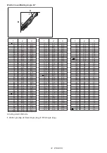
Page 31: ...2 0 1 6 1 2 0 8 0 4 0 0 12 3 12 0 11 6 11 3 11 0 10 7 10 3 10 0 9 7 9 4 9 0 8 7 8 4 8 1 7 8 7 5 7 1 6 8 6 5 6 2 5 9 5 6 5 3 4 9 4 6 4 3 4 0 3 7 3 4 3 1 2 8 2 5 2 2 1 8 1 5 1 2 0 9 0 6 0 3 0 0 141 142 143 144 145 146 147 148 149 150 151 152 153 154 155 156 157 158 159 160 161 162 163 164 165 166 167 168 169 170 171 172 173 174 175 176 177 178 179 180 43 0 42 8 42 5 42 2 41 9 41 7 41 4 41 1 40 8 40 ...

Page 32: ...0 0 14 1 13 7 13 3 12 9 12 6 12 2 11 8 11 5 11 1 10 7 10 4 10 0 9 6 9 3 8 9 8 5 8 2 7 8 7 5 7 1 6 7 6 4 6 0 5 7 5 3 5 0 4 6 4 3 3 9 3 5 3 2 2 8 2 5 2 1 1 8 1 4 1 1 0 7 0 4 0 0 141 142 143 144 145 146 147 148 149 150 151 152 153 154 155 156 157 158 159 160 161 162 163 164 165 166 167 168 169 170 171 172 173 174 175 176 177 178 179 180 37 8 37 5 37 3 37 1 36 8 36 6 36 4 36 1 35 9 35 6 35 4 35 1 34 9...

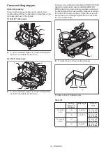
Page 33: ...its WALL CONTACT EDGE against the guide fence and its CEILING CONTACT EDGE against the crown molding stoppers as shown in the figure Adjust the crown molding stoppers according to the size of the crown molding Tighten the screws to secure the crown molding stoppers Refer to the table C for the miter angle 1 2 1 Guide fence 2 Crown molding stopper a b c d 1 2 1 Inside corner 2 Outside corner Table ...

Page 34: ... results and kickback which may result in serious personal injury For a dado type cut perform as follows 1 Adjust the lower limit position of the circular saw blade using the adjusting screw and the stopper arm to limit the cutting depth of the circular saw blade Refer to the section for stopper arm 2 After adjusting the lower limit position of the circu lar saw blade cut parallel grooves across t...

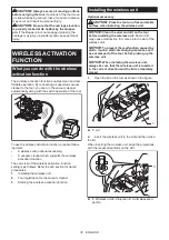
Page 35: ...wireless activation function setting is as follows Refer to each section for detail procedures 1 Installing the wireless unit 2 Tool registration for the vacuum cleaner 3 Starting the wireless activation function Installing the wireless unit Optional accessory CAUTION Place the tool on a flat and stable surface when installing the wireless unit NOTICE Clean the dust and dirt on the tool before ins...

Page 36: ...Avoid turning the following switches on during tool registration switch trigger on the tool vacuum switch on the tool power switch on the vacuum cleaner NOTE Refer to the instruction manual of the vacuum cleaner too If you wish to activate the vacuum cleaner along with the switch operation of the tool finish the tool registra tion beforehand 1 Install the batteries to the vacuum cleaner and the to...

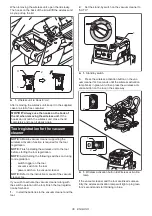
Page 37: ... out of any cutting operation 1 Install the wireless unit to the tool 2 Connect the hose of the vacuum cleaner with the tool 3 Set the stand by switch on the vacuum cleaner to AUTO 1 1 Stand by switch 4 Push the wireless activation button on the tool briefly The wireless activation lamp will blink in blue 1 2 1 Wireless activation button 2 Wireless activation lamp 5 Pull the switch trigger of the ...

Page 38: ...on function Refer to the table below for the meaning of the lamp status Status Wireless activation lamp Description Color On Blinking Duration Standby Blue 2 hours The wireless activation of the vacuum cleaner is available The lamp will automatically turn off when no operation is performed for 2 hours When the tool is running The wireless activation of the vacuum cleaner is available and the tool ...

Page 39: ...nd then become red After that press the wireless activation button on the tool in the same way 1 1 2 2 1 Wireless activation button 2 Wireless activation lamp If the cancellation is performed successfully the wire less activation lamps will light up in red for 2 seconds and start blinking in blue NOTE The wireless activation lamps finish blinking in red after 20 seconds elapsed Press the wireless ...

Page 40: ...vacuum cleaner is turned on Push the wireless activation button briefly and perform the tool registration cancellation procedures again The tool registration procedures for the tool or vacuum cleaner have not finished Perform the tool registration procedures for both the tool and the vacuum cleaner at the same timing Radio disturbance by other appliances which generate high intensity radio waves K...

Page 41: ...ned at the factory but rough handling may have affected the alignment If your tool is not aligned properly perform the following Miter angle Lower the handle fully and lock it in the lowered position with the stopper pin Push the carriage towards the guide fence Rotate the grip counterclockwise and have the turn base ready for the positive stop function using the lock lever Then loosen the screws ...

Page 42: ...stment Loosen the knob and fully tilt the carriage to the side that you want to check Check if the pointer indicates the 45 position in the bevel angle scale 1 1 Knob If the pointer does not indicate the 45 position align it with the 45 position by turning the adjusting bolt in the bevel angle scale on the opposite side of the base 1 2 1 Left 45 adjusting bolt 2 Right 45 adjusting bolt Cleaning la...

Page 43: ...njury WARNING Only use the Makita accessory or attachment for its stated purpose Misuse of an accessory or attachment may result in serious personal injury If you need any assistance for more details regard ing these accessories ask your local Makita Service Center Carbide tipped saw blades Vertical vise Horizontal vise Crown molding stopper set Dust bag Triangular rule Hex wrench Wireless unit St...

Page 44: ...7 mm 1 11 16 x 7 3 4 60 derecho e izquierdo 71 mm x 152 mm 2 13 16 x 6 91 mm x 139 mm 3 5 8 x 5 1 2 Capacidades de corte especiales Tipo de corte Capacidad de corte Moldura tipo corona de 45 usando el tope para moldura de corona 168 mm 6 5 8 Zócalo usando la prensa horizontal 133 mm 5 1 4 Debido a nuestro continuo programa de investigación y desarrollo las especificaciones aquí incluidas están suj...

Page 45: ...objetos cortantes o piezas móvi les Los cables dañados o enredados aumentan el riesgo de sufrir una descarga eléctrica 5 Cuando utilice una herramienta eléctrica en exteriores utilice un cable de extensión apro piado para uso en exteriores La utilización de un cable apropiado para uso en exteriores redu cirá el riesgo de que se produzca una descarga eléctrica 6 Si no es posible evitar usar una her...

Page 46: ...bajo a realizar Si utiliza la herramienta eléctrica para realizar operaciones distintas de las indicadas podrá presentarse una situación peligrosa 8 Mantenga los mangos y superficies de asi miento secos limpios y libres de aceite o grasa Los mangos y superficies de asimiento resbalosos no permiten una manipulación segura ni el control de la herramienta en situaciones inesperadas 9 Cuando vaya a ut...

Page 47: ...ntes de cortar Si la pieza de trabajo está doblada o torcida sujétela con la parte arqueada exterior orientada hacia la guía Asegúrese siempre de que no haya ningún espacio entre la pieza de trabajo la guía y la mesa a lo largo de la línea de corte Las piezas de trabajo dobladas o torcidas podrían voltearse o desplazarse y causar que el disco de la sierra que está girando se atore mientras corta E...

Page 48: ...ramienta desatendida mien tras esté en marcha Desconecte la alimenta ción No deje la herramienta hasta que se haya detenido completamente 5 No utilice la sierra sin los protectores pues tos Verifique que el protector del disco cierre debidamente antes de cada uso No utilice la sierra si el protector del disco no se mueve libremente y se cierra instantáneamente No sujete ni ate el protector del dis...

Page 49: ...arme ni modifique el cartucho de bate ría Podría ocurrir un incendio calor excesivo o una explosión 3 Si el tiempo de operación se ha acortado en exceso deje de operar de inmediato Podría correrse el riesgo de sobrecalentamiento posibles quemaduras e incluso explosión 4 En caso de que ingresen electrolitos en sus ojos enjuáguelos bien con agua limpia y con sulte de inmediato a un médico Esto podrí...

Page 50: ...e batería sáquelo de la herramienta o del cargador 5 Cargue el cartucho de batería si no va a utili zarlo durante un período prolongado más de seis meses Instrucciones importantes de seguridad para la unidad inalámbrica 1 No desarme ni modifique la unidad inalámbrica 2 Mantenga la unidad inalámbrica alejada de los niños pequeños En caso de ingerirla accidentalmente solicite atención médica de inme...

Page 51: ...sario Vuelva a colocar la tapa si ésta se sale de la herramienta 29 Reemplace la tapa de la ranura si llega a per derse o dañarse GUARDE ESTAS INSTRUCCIONES DESCRIPCIÓN DE LAS PIEZAS 1 1 2 3 4 5 9 6 7 8 11 10 12 13 14 15 16 17 18 19 20 21 22 23 25 24 26 27 1 Pomo para el ángulo de bisel 2 Llave hexagonal 3 Tornillo de ajuste para la posición del límite inferior 4 Perno de ajuste para la máxima cap...

Page 52: ...el ángulo de bisel 7 Marcador para el ángulo de bisel 8 Perno de ajuste de 45 para el ángulo de bisel 9 Palanca de la aldabilla para el ángulo de bisel 10 Palanca de liberación para el ángulo de bisel de 48 11 Guía lateral guía superior 12 Guía lateral guía inferior 13 Clavija de retención para la elevación del carro 14 Bloqueo del eje INSTALACIÓN Instalación de la perilla Atornille el eje roscado...

Page 53: ...Botón de bloqueo 4 Manguito 5 Puerto superior 6 Puerto inferior Para extraer el codo de la manguera del puerto jale del codo mientras oprime el botón de bloqueo 1 2 1 Botón de bloqueo 2 Codo Para quitar el manguito de la manguera del puerto tire del manguito mientras presiona los botones de tope de ambos lados del puerto 1 2 1 Botón de tope 2 Manguito Montaje en un banco de trabajo Cuando la herra...

Page 54: ...linee la lengüeta sobre el cartucho de batería con la ranura en la carcasa y deslícela hasta su lugar Insértelo por completo hasta que se fije en su lugar con un pequeño clic Si puede ver el indicador rojo como se muestra en la ilustración este no ha quedado asegurado por completo PRECAUCIÓN Introduzca siempre com pletamente el cartucho de batería hasta que el indicador rojo no pueda verse Si no p...

Page 55: ...el sistema de protección de batería esté en funcionamiento Bloqueo de la empuñadura PRECAUCIÓN Siempre sostenga la empu ñadura al liberar la clavija de retención De lo contrario la empuñadura se levanta de golpe y puede provocar una lesión La empuñadura se puede bloquear en la posición descendida o en la posición elevada con la clavija de retención Baje o suba la empuñadura completamente y luego t...

Page 56: ...dañarlo Siga las instrucciones paso a paso enumeradas sobre cómo prepararse para la limpieza 1 Asegúrese de apagar la herramienta y retirar el cartucho de batería 2 Gire el perno hexagonal en sentido inverso al de las manecillas del reloj usando la llave hexagonal sumi nistrada mientras sostiene la cubierta central 3 Levante el protector del disco y la cubierta central 4 Una vez finalizada la limp...

Page 57: ...te en bisel izquierdo o derecho extraiga siempre las guías laterales superiores y la prensa vertical 7 Apriete los tornillos delanteros no los apriete por completo 8 Empuje el carro hacia las guías laterales por com pleto y luego ajuste los paneles de corte de tal forma que éstos apenas hagan contacto con los costados de los dientes del disco 9 Apriete los tornillos traseros no los apriete por com...

Page 58: ...a empuñadura completamente hacia abajo para asegurar que el disco de la sierra circular no haga contacto con ninguna pieza de la base inferior Reajuste ligeramente en caso necesario ADVERTENCIA Tras la colocación de un disco de la sierra circular nuevo y con el cartucho de batería retirado asegúrese siempre de que el disco de la sierra circular no haga contacto con ninguna pieza de la base inferio...

Page 59: ...te la empuñadura 1 Gire la perilla en sentido inverso al de las maneci llas del reloj Luego presione y mantenga presionada la palanca de bloqueo hasta la posición de desbloqueo 2 Sostenga y oscile la perilla de lado a lado para girar la base giratoria 3 Alinee el marcador con su ángulo deseado en la escala del ángulo de inglete 4 Libere la palanca de bloqueo y apriete la perilla 2 3 4 1 1 Perilla ...

Page 60: ...ente elevado AVISO Cuando cambie los ángulos de bisel ase gúrese de volver a posicionar adecuadamente los paneles de corte tal como se explica en la sección para posicionamiento de los paneles de corte AVISO No apriete el pomo del soporte de corredera demasiado fuerte El hacerlo podría causar una avería en el mecanismo de bloqueo del ángulo de bisel Inclinación del disco de la sierra circular a la...

Page 61: ...ón del disco de la sierra circular con función de tope de seguridad Esta sierra de inglete emplea la función de tope de seguridad Usted puede ajustar rápidamente el ángulo tanto del lado derecho como del izquierdo en 22 5 y 33 9 1 Rote el pomo del soporte de corredera en sentido inverso al de las manecillas del reloj 2 Incline el carro cerca del ángulo de tope de seguridad deseado mientras levanta...

Page 62: ...herramienta con un interruptor que no funcione correctamente es SUMAMENTE PELIGROSA y debe ser reparada antes de continuar su uso o podría causar lesiones personales graves ADVERTENCIA NUNCA inhabilite el botón de desbloqueo manteniéndolo presionado con cinta adhesiva o mediante otro método El uso de un interruptor con un botón de desbloqueo inha bilitado puede ocasionar una operación accidental y...

Page 63: ...io NOTA Asegúrese de apagar el interruptor de la lámpara después de usarla porque encender la luz consume la energía de la batería NOTA La luz se apaga automáticamente 5 minutos después de que interrumpe la operación Función eléctrica Freno eléctrico La herramienta está equipada con un freno eléctrico para el disco Si de manera consistente la herramienta no cesa de funcionar rápidamente después de...

Page 64: ...segúrese de que éste quede instalado firmemente La sujeción suelta del disco de la sierra circular podría causar lesiones persona les graves Extracción del disco Para retirar el disco de la sierra circular siga los pasos siguientes 1 Bloquee el carro en la posición elevada tirando y girando la clavija de retención en una posición bloqueada 1 2 3 1 Clavija de retención 2 Posición desbloqueada 3 Pos...

Page 65: ...del disco de la sierra circular 2 Instale la brida exterior y el perno de cabeza hexagonal y luego use la llave hexagonal para apretar el perno de cabeza hexagonal en sentido inverso al de las manecillas del reloj y firmemente mientras presiona el bloqueo del eje 1 2 3 4 5 6 1 Perno de cabeza hexagonal rosca hacia la izquierda 2 Brida exterior 3 Disco de la sierra circular 4 Brida interior 5 Eje 6...

Page 66: ...iones personales graves y causar daños a la herramienta y o la pieza de trabajo ADVERTENCIA Al cortar una pieza de tra bajo de un tamaño mayor que la base de la sierra de inglete la pieza deberá apoyarse sobre toda su longitud más allá de la base de apoyo man teniendo la pieza nivelada Un apoyo adecuado de la pieza de trabajo ayudará a evitar que el disco se trabe ocasionando un posible retroceso ...

Page 67: ...ajo no queda debidamente asegurada contra las guías el material podría despla zarse durante la operación de corte ocasionando daños al disco de la sierra circular y salir disparado causando la pérdida de control y lesiones personales graves La prensa vertical se puede instalar ya sea del lado izquierdo o derecho de la base Inserte la varilla de la prensa en el orificio de la base 1 2 3 2 1 Prensa ...

Page 68: ...uro de la prensa Si gira la tuerca de la prensa en sentido inverso al de las manecillas del reloj la prensa se liberará y podrá desplazarse rápidamente hacia adentro y hacia afuera Para sujetar la pieza de trabajo empuje el seguro de la prensa hacia adelante hasta que la placa de la prensa haga contacto con la pieza de trabajo y gire la tuerca de la prensa en el sentido de las manecillas del reloj...

Page 69: ...n elemento cuadrado de acero horizontalmente contra la guía lateral 3 Mientras la barra está horizontal contra la guía lateral reposicione la guía auxiliar de manera que la cara de la guía auxiliar quede horizontal contra la barra Una vez hecho esto apriete los pernos 1 2 4 4 3 1 Perno 2 Guía auxiliar 3 Guía lateral 4 Barra rígida OPERACIÓN Esta herramienta está diseñada para cortar productos de m...

Page 70: ...la pieza de trabajo con el tipo adecuado de prensa 3 Encienda la herramienta sin que el disco de la sierra circular haga contacto alguno y espere a que éste adquiera velocidad completa antes de bajar la empuñadura 4 Luego baje lentamente la empuñadura a la posi ción completamente hacia abajo para realizar el corte en la pieza de trabajo 5 Una vez finalizado el corte apague la herramienta y espere ...

Page 71: ...fuerza de manera perpendicular a la base giratoria o si la dirección de la presión es modificada durante el corte la precisión del corte se verá afectada 1 Retire la guía superior del lado donde vaya a inclinar el carro 2 Desbloquee la clavija de retención 3 Ajuste el ángulo de bisel conforme al procedi miento explicado en la sección para ajuste del ángulo de bisel Luego apriete el pomo 4 Asegure ...

Page 72: ...moldura en la figura Ángulo de bisel Ángulo de inglete Tipo de 52 38 Tipo de 45 Tipo de 52 38 Tipo de 45 Para rincón interno a Izquierda 33 9 Izquierda 30 Derecha 31 6 Derecha 35 3 b Izquierda 31 6 Izquierda 35 3 Para rincón externo c d Derecha 31 6 Derecha 35 3 Tabla B Posición de la moldura en la figura Borde de la moldura contra la guía lateral Pieza terminada Para rincón interno a El borde de ...

Page 73: ...l lado derecho del disco b El borde de contacto con el techo deberá estar contra la guía lateral Para rincón externo c La pieza terminada estará del lado izquierdo del disco d El borde de contacto con la pared deberá estar contra la guía lateral Ejemplo En caso de cortar una moldura tipo corona de 52 38 para la posición a en la figura de arriba Incline y asegure la posición del ángulo de bisel a 3...

Page 74: ... 6 1 2 0 8 0 4 0 0 12 3 12 0 11 6 11 3 11 0 10 7 10 3 10 0 9 7 9 4 9 0 8 7 8 4 8 1 7 8 7 5 7 1 6 8 6 5 6 2 5 9 5 6 5 3 4 9 4 6 4 3 4 0 3 7 3 4 3 1 2 8 2 5 2 2 1 8 1 5 1 2 0 9 0 6 0 3 0 0 141 142 143 144 145 146 147 148 149 150 151 152 153 154 155 156 157 158 159 160 161 162 163 164 165 166 167 168 169 170 171 172 173 174 175 176 177 178 179 180 43 0 42 8 42 5 42 2 41 9 41 7 41 4 41 1 40 8 40 5 40 ...

Page 75: ... 7 13 3 12 9 12 6 12 2 11 8 11 5 11 1 10 7 10 4 10 0 9 6 9 3 8 9 8 5 8 2 7 8 7 5 7 1 6 7 6 4 6 0 5 7 5 3 5 0 4 6 4 3 3 9 3 5 3 2 2 8 2 5 2 1 1 8 1 4 1 1 0 7 0 4 0 0 141 142 143 144 145 146 147 148 149 150 151 152 153 154 155 156 157 158 159 160 161 162 163 164 165 166 167 168 169 170 171 172 173 174 175 176 177 178 179 180 37 8 37 5 37 3 37 1 36 8 36 6 36 4 36 1 35 9 35 6 35 4 35 1 34 9 34 6 34 4 ...

Page 76: ... DE CONTACTO CON LA PARED apoyado contra la guía lateral y el BORDE DE CONTACTO CON EL TECHO apoyado contra los topes para moldura de corona tal como se muestra en la ilustración Ajuste los topes para moldura de corona según el tamaño de la moldura de corona Apriete los tornillos para asegurar los topes para moldura de corona Consulte la tabla C para ver el ángulo de inglete 1 2 1 Guía lateral 2 T...

Page 77: ...n corte con el brazo de retención en la posición incorrecta podría ocasionar resultados ines perados en el corte así como retrocesos bruscos que resulten en lesiones personales graves Para realizar un corte de ranuras haga lo siguiente 1 Ajuste la posición del límite inferior del disco de la sierra circular con el tornillo de ajuste y el brazo de retención para restringir la profundidad de corte d...

Page 78: ... tenga preparado lo siguiente Una unidad inalámbrica accesorios opcionales Una aspiradora compatible con la función de activación inalámbrica A continuación se presenta la descripción general del ajuste de la función de activación inalámbrica Consulte cada sección para ver los procedimientos a detalle 1 Instalación de la unidad inalámbrica 2 Registro de la herramienta para la aspiradora 3 Inicio d...

Page 79: ...nder los siguientes interruptores durante el registro de la herramienta el gatillo interruptor de la herramienta el interruptor de aspiradora de la herramienta el interruptor de alimentación de la aspiradora NOTA Consulte también el manual de instrucciones de la aspiradora Si desea activar la aspiradora junto con el interruptor de la herramienta termine antes con el registro de la herramienta 1 In...

Page 80: ...tomáticamente junto con el interruptor de la herramienta Tire del gatillo interruptor de la herramienta para hacer funcionar la aspiradora durante la operación La aspiradora también empieza a funcionar al oprimir el botón de aspiradora de la herra mienta por cualquier operación de cortado 1 Instale la unidad inalámbrica en la herramienta 2 Conecte la manguera de la aspiradora a la herramienta 3 Aj...

Page 81: ...l botón de aspiradora debido a que otro usuario está utilizando la función de acti vación inalámbrica Descripción del estado de la luz indicadora de activación inalámbrica 1 1 Luz indicadora de activación inalámbrica La luz indicadora de activación inalámbrica muestra el estado de la función de activación inalámbrica Consulte la tabla a continuación para ver qué significa el estado de la luz indic...

Page 82: ...ctivación inalámbrica en la herramienta de la misma manera 1 1 2 2 1 Botón de activación inalámbrica 2 Luz indica dora de activación inalámbrica Si la cancelación se realiza exitosamente las luces indicadoras de activación inalámbrica se encenderán en rojo durante 2 segundos y comenzarán a parpadear en azul NOTA Las luces indicadoras de activación inalám brica terminarán parpadeando en rojo despué...

Page 83: ... Instale la unidad inalámbrica correctamente La terminal de la unidad inalámbrica y o la ranura está sucia Retire con cuidado el polvo y la suciedad en la terminal de la unidad inalámbrica y limpie la ranura El interruptor de modo en espera en la aspiradora no está ajustado en AUTO Ajuste el interruptor de modo en espera en la aspiradora en AUTO No hay suministro de energía Suministre energía a la...

Page 84: ...stancias La perturbación radioeléctrica generada por otros aparatos que emiten ondas de radio de alta intensidad Mantenga la herramienta y la aspiradora lejos de aparatos tales como dispositivos Wi Fi y hornos de microondas La aspiradora está funcionando mientras ninguno de los interrup tores de la herramienta están en funcionamiento Otros usuarios están usando la activa ción inalámbrica de la asp...

Page 85: ...echo como el izquierdo con la posición de 0 en la escala del ángulo de inglete y luego apriete el tornillo en el marcador 1 2 1 Regla triangular 2 Marcador Ángulo de bisel Ángulo de bisel de 0 Empuje el carro hacia las guías laterales y bloquee el movi miento de deslizamiento con la clavija de retención Baje el carro por completo y bloquéelo en la posición hacia abajo con la clavija de retención G...

Page 86: ... el lente Si el lente no sale afloje el tornillo todavía más AVISO Utilice un paño seco para quitar la sucie dad de la lente de la lámpara Tenga cuidado de no rayar la lente de la lámpara ya que la ilumina ción podría disminuir AVISO No utilice disolventes ni limpiadores a base de petróleo en el lente La luz LED es difícil de visualizar si el lente para la luz se llega a ensuciar Limpie el lente e...

Page 87: ...ensa vertical Prensa horizontal Conjunto de topes para moldura de corona Bolsa recolectora de polvo Regla triangular Llave hexagonal Unidad inalámbrica Juego de pedestales Base inferior Batería y cargador originales de Makita NOTA Algunos de los artículos en la lista pueden incluirse en el paquete de la herramienta como acce sorios estándar Éstos pueden variar de país a país GARANTÍA LIMITADA DE M...

Page 88: ...ados por el lijado aserrado esmerilado taladrado y otras actividades de la construcción contienen sustancias químicas reconocidas por el Estado de California como causantes de cáncer defectos de nacimiento y otros peligros de reproducción Algunos ejemplos de estos productos químicos son plomo de pinturas a base de plomo sílice cristalino de ladrillos y cemento y otros productos de albañilería y ar...

Reviews: