7
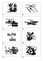
To adjust the scale plates, loosen the wing bolts securing
the guide rule. Move the guide rule until the inside of the
guide rule is flush with the inner side of the cutter blade.
Tighten the wing bolts to secure the guide rule. Loosen
the screws securing the scale plates. Move the scale
plates so that “0” on the scale plates are aligned with the
inside of the guide rule. Tighten the screws to secure the
scale plates.
(Fig. 9)
Switch action
To start the tool, simply pull the trigger. Release the
trigger to stop. For continuous operation, pull the trigger
and then push in the lock button. To stop the tool from the
locked position, pull the trigger fully, then release it.
(Fig. 10)
CAUTION:
Before plugging in the tool, always check to see that the
trigger switch actuates properly and returns to the “OFF”
position when released.
Operation
Rest the front end of the base on the workpiece surface
with the guide rule contacting flush with the side of the
workpiece and without the cutter blade making any
contact with the workpiece. Switch on and wait until the
cutter blade attains full speed. Then move the tool gently
forward.
(Fig. 11)
NOTE:
If the tool is tilted at the start or the end of cutting, the end
of the workpiece will be badly gouged. Hold the base of
the tool flush with the workpiece at all times.
Shiplapping rule
Attach the shiplapping rule to the guide rule and slide the
guide rule into the base of the tool. Move the guide rule to
set the cutting width, i.e., the protrusion of the cutter blade
in relation to the side of the shiplapping rule.
(Fig. 12 &
13)
Removing or installing saw blade
CAUTION:
Always be sure that the tool is switched off and unplugged
before removing or installing the blade.
To install the saw blade, first remove the hex nut, outer
flange and cutter blade as described in “Removing or
installing cutter blade”.
If the safety cover is locked with the stopper, unlock the
safety cover. To unlock the safety cover, push it slightly in
clockwise direction and the stopper will release the safety
cover.
WARNING:
When using this tool as a circular saw, always keep the
safety cover in place and in working order. Never wedge
or tie the safety cover.
(Fig. 14)
Remove the depth adjusting wing bolt and move the base
down. Mount the inner flange 56, saw blade, outer
flange 56, outer flange and hex nut onto the spindle in the
order, making sure that the saw blade is installed with
teeth pointing up at the front of the tool.
(Fig. 15)
Reinstall the depth adjusting wing bolt and tighten it to
secure the base. Then use the two wrenches to tighten
the hex nut securely.
(Fig. 16)
To remove the saw blade, follow the installation
procedure in reverse.
MAINTENANCE
CAUTION:
• Always be sure that the tool is switched off and
unplugged before attempting to perform inspection or
maintenance.
• Never use gasoline, benzine, thinner, alcohol or the
like. Discoloration, deformation or cracks may result.
Replacing carbon brushes
Remove and check the carbon brushes regularly. Replace
when they wear down to the limit mark. Keep the carbon
brushes clean and free to slip in the holders. Both carbon
brushes should be replaced at the same time. Use only
Makita carbon brushes.
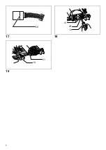
(Fig. 17)
Use a screwdriver to remove the rear cover.
(Fig. 18)
Use a screwdriver to remove the brush holder caps. Take
out the worn carbon brushes. Insert the new ones and
secure the brush holder caps.
(Fig. 19)
To maintain product SAFETY and RELIABILITY, repairs,
any other maintenance or adjustment should be
performed by Makita Authorized or Factory Service
Centers. Always use Makita replacement parts.
OPTIONAL ACCESSORIES
CAUTION:
These accessories or attachments are recommended for
use with your Makita tool specified in this manual. The
use of any other accessories or attachments might
present a risk of injury to persons. The accessories or
attachments should be used only in the proper and
intended manner.
• Cutter blades
• Combination saw blade (Blade dia.: 190 mm (7-1/2”))
• Cross cut saw blade (Blade dia.: 190 mm (7-1/2”))
• Dressing stone
• Wrench 19
• Wrench 21
• Guide rule
• Shiplapping scale
• Flange 35 (For cutter blade width 2.4 mm (3/32”) –
7.5 mm (5/16”))
• Inner flange 56
• Outer flange 56 (For circular saw)
• Guide rule (For circular saw)
• Stand
NOTE:
Some items in the list may be included in the tool package
as standard accessories. They may differ from country to
country.
Summary of Contents for 3501N
Page 2: ...2 1 2 3 4 5 6 7 8 1 2 3 6 7 4 5 8 6 9 10 11 6 12 8 9 13 14 15 16 17 2 18 ...
Page 3: ...3 9 10 11 12 13 14 15 16 19 17 16 20 21 22 23 18 24 25 8 26 6 27 28 3 4 5 7 ...
Page 4: ...4 17 18 19 29 16 30 19 31 19 ...
Page 19: ...19 ...
Page 20: ...ALA Makita Corporation Anjo Aichi Japan 883008 374 www makita com ...


