P
4
/
6
R
epair
[1] DISASSEMBLY/ASSEMBLY
[1]-2. Motor Assembly
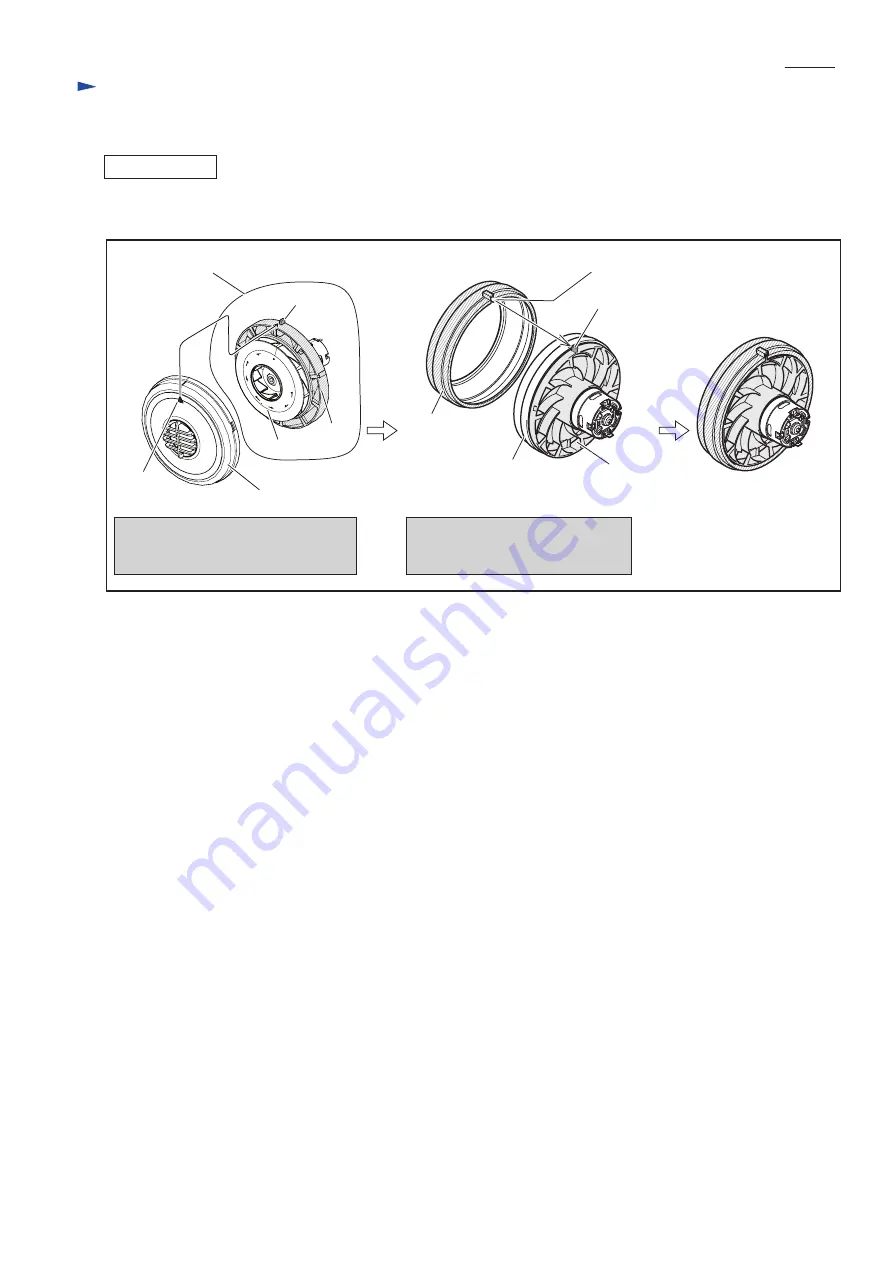
ASSEMBLING
Fan cover
Triangle
mark
While aligning Triangle mark to the
protrusion of Base, assemble Fan cover
to Base.
Fan cover
Base
Rubber ring
Fan 82
Base
protrusion
protrusion
Motor assembly
(1) Assemble Fan cover and Rubber ring as illustrated in Fig. 10.
(2) Connect Receptacles to the terminals of DC Motor. (Fig. 8, Fig. D-2 in Wiring diagram)
(3) Take the disassembling step in reverse. Refer to Figs. 7 to
3.
groove
Fitting the groove of Rubber ring
to the protrusion of Base, assemble
Rubber ring to Base.
Note: The wrong aligning and
fitting make it impossible
to match Housing set L
and R completely.
Fig. 10
(1) Remove Rear cover as illustrated in Fig. 5.
(2) Remove Battery from Housing set. And then disconnect the connector of Controller’s Lead wires from the connector of
Battery as illustrated in Fig. 6. Now Battery can be replaced.
[1]-3. Battery


