

C
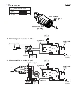
ircuit diagram P 10 / 11
1
1
2
2
Insulated
terminal
Insulated
terminal
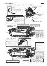
Color index of lead wires
Black
White
Orange
Purple
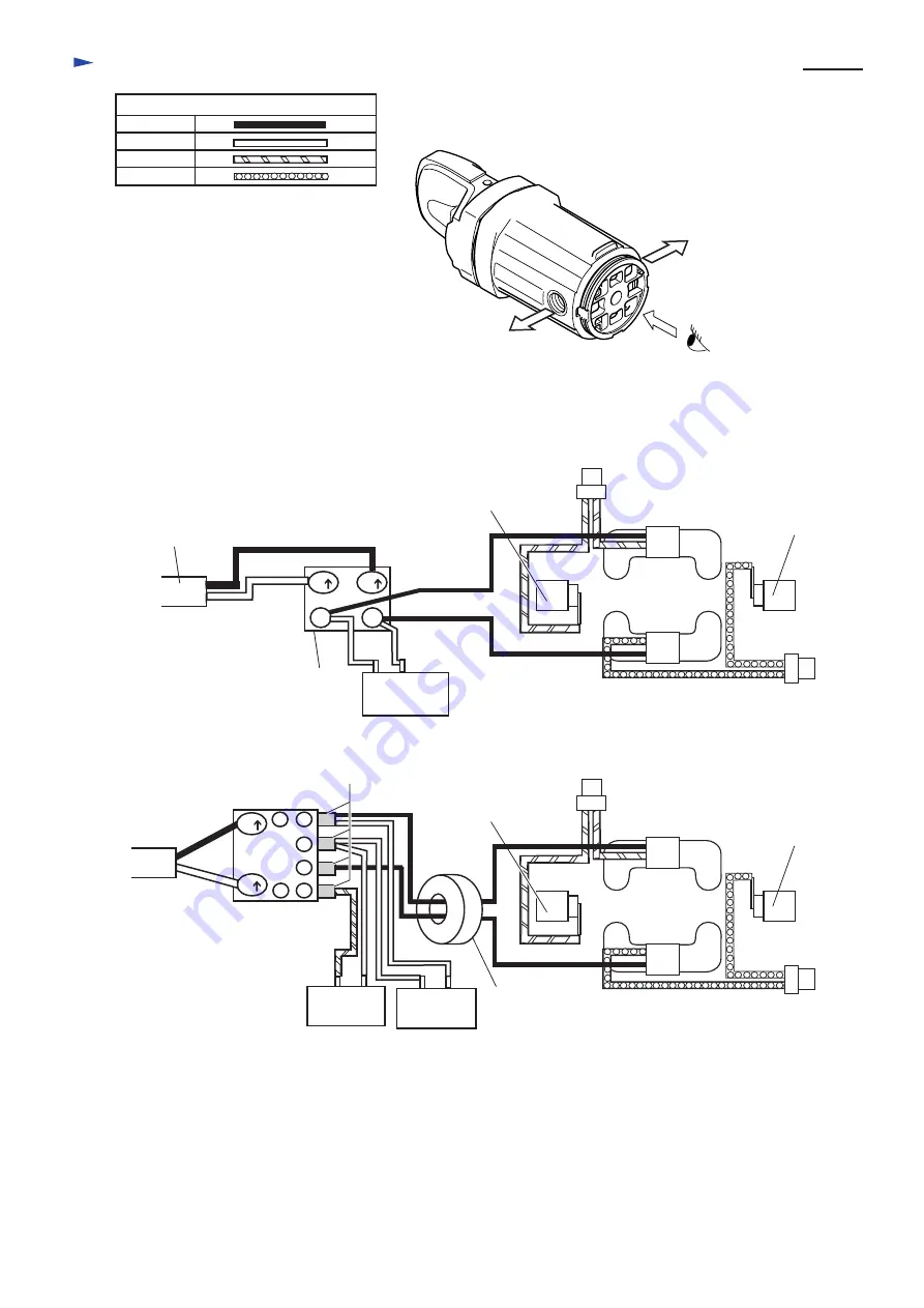
Brush holder
(left)
Field
Brush holder
(right)
Insulated
terminal
Insulated
terminal
Brush holder
(left)
Field
Brush holder
(right)
Power supply cord
1. Circuit diagram for model 4112H
2. Circuit diagram for model 4112HS
Soft start
circuit
1
5
2
2
1
2
1
2
Switch
Switch
Noise
suppressor
Noise
suppressor
Insulated receptacle
Line filter
(Left)
(Right)
Brush holder
Brush holder


