D
isassembly and assembly
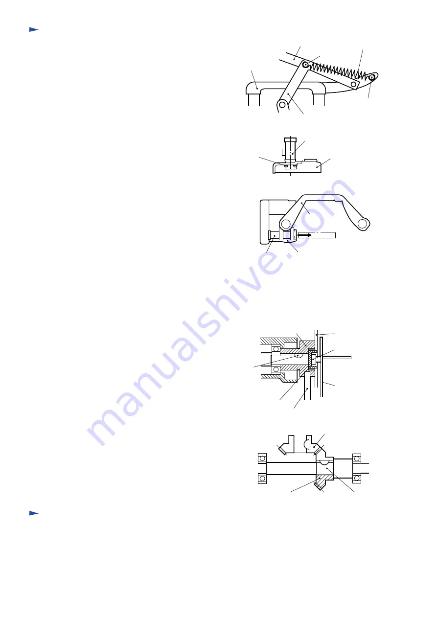
Remove stepped pins that connect lever pipe and
rink plate. Turn lever pipe to the right side of the
tension spring until it stops and remove the tension
spring. When hanging a tension spring, direction of
hook should be as shown in the figure.
1)
A
djustment of saw blade
When a diameter of vertical saw becomes small because of grinding, insert a bar into the outer hole
of the vertical saw flange and stop the rotation. Use wrench 4-13 and turn hex. bolt in the rear side
of the lateral saw shaft to move the vertical saw forward and backward, and align the lateral saw to
the tip of the vertical saw. In the case of the ground lateral saw, make adjustment by moving the
lateral saw's gear case right and left.
1)
Remove four cross-slot pan-head screws inside the
center gear housing, and disassemble vertical saw
support and center gear housing.
2)
Lever pipe
Stepped pin
Pole supporter
Tension spring
Stepped pin
Link plate
Remove gear housing of lateral saw section from the
vertical saw support, and bevel gear of the lateral
saw side will be disengaged. Separate saw blade
shaft from vertical saw support, and the vertical saw
shaft can be removed from the bevel gear.
6)
Insert a bar into the outer hole of inner flange and
remove hex. socket bolt by using a wrench so that
both inner flange 50 and flange 25 can be removed
from saw blade shaft.
5)
Replacement of carbon brush
Fully open the lever 240 outside and remove holder cap from the rear cover's hole by using a screwdriver
then remove the carbon brush.
4)
Remove spring pin that connects slide pipe and vertical
saw support and pull out the slide pipe to the direction
as shown in the figure, then disassemble the slide
frame and vertical saw support.
3)
Vertical saw support
Center gear housing
Cross-slot
pan-head screw
Slide frame
Vertical saw support
Slide pipe
Inner flange 50
Bar
Flange 25
Woodruff
key
Vertical saw
Hex. socket bolt
Wrench
Vertical saw's bevel gear
Saw blade
Vertical saw shaft bevel gear
Inner flange 50 of vertical shaft


