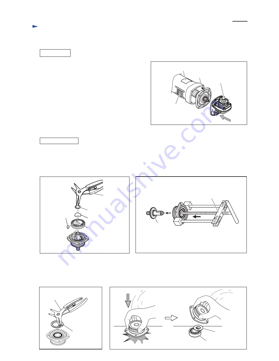
background image

Fig. 6

Notch

Switch lever

Spindle

Name plate 

Assemble by reversing the disassembly procedure. 

(Refer to 

Figs. 5, 4, 3  and 2)

Note

: Assemble Gear housing cover together with Armature

while facing its notch to the same side as Name plate. (

Fig. 6

)

And then, assemble Gear housing while facing Spindle to the 

same side as the notch and Name plate. (

Fig. 6

)

ASSEMBLING

 4

8

R

epair

[3] DISASSEMBLY/ASSEMBLY

[3] -1. Replacing Spiral Bevel Gear 10 (cont.) 

Note

: The gear and the ball bearing can be replaced without disassembling the motor section.

(1) Remove Retaining ring S-12 with 1R291, then remove Wave washer 12. Spiral bevel gear (large) can be removed 

     from Spindle by hand. And then, remove Woodruff key 4 from Spindle. (

Fig. 7

)

(2) Remove Spindle from Bearing box using 1R045. (

Fig. 8

)   

[3] -2. Replacing Spiral Bevel Gear 37 and Ball Bearing 6201DDW

DISASSEMBLING

Fig. 7

Fig. 8

Retaining ring S-12
Wave washer 12

1R291

Spiral bevel gear 37

Woodruff key 4

Spindle with 

Labyrinth Ring

1R045

Fig. 9

Fig. 10

Retaining ring

R-32

1R291

Ball bearing

6201DDW

Flat washer 12

(3) Remove retaining ring R-32 with 1R291. (

Fig. 9

)

(4) Remove Ball bearing 6201DDW together with Flat washer 12 from Bearing box by tapping Bearing box straight down

      against workbench. (

Fig. 10

)

Note

: If it is difficult to remove it by hand tapping, use arbor press.

Summary of Contents for 9556HN

Page 1: ...nput Output Max Output W 110 120 220 230 240 8 0 7 5 4 0 3 8 3 7 50 60 50 60 50 60 50 60 50 60 840 840 840 840 840 500 500 500 500 500 1 000 1 000 1 000 1 000 1 000 Current A Note The standard equipme...

Page 2: ...rasion 2 LUBRICATION Item No Description O ring 26 9 Whole portion Gear housing complete 18 a 18 a Front view Six air holes Note in Lubrication Gear housing complete of 18 b which has two air holes is...

Page 3: ...wing four 4x30 Tapping screws Fig 3 3 Remove Gear housing cover from Motor housing together with Armature by levering with a slotted screwdriver fit to the notch on the Gear housing cover Fig 4 4 Remo...

Page 4: ...ring S 12 with 1R291 then remove Wave washer 12 Spiral bevel gear large can be removed from Spindle by hand And then remove Woodruff key 4 from Spindle Fig 7 2 Remove Spindle from Bearing box using 1R...

Page 5: ...shing Pin cap with finger Fig 11 Note Do not pull off Shoulder pin 4 without holding Pin cap because Compression spring 8 would sling Pin cap Push Shoulder pin 4 through Gear housing and Compression s...

Page 6: ...n Figs D 3 D 6 Brush holder A Brush holder B Motor housing with Field view from Rear cover side Spindle Connect to Brush holder B Connect to Switch terminals Lead wire black Lead wire black Lead Wires...

Page 7: ...not used for some countries Route Lead wire of Power supply cord to Switch terminal No 2 so that it runs around boss A Motor housing Bottom view Motor housing Boss A Be sure that Field lead wires are...

Page 8: ...g is not used for some countries Sensormatic tag anti theft tag Noise suppressor Put Sensormatic tag in this space Noise suppressor Be sure that Field lead wires are tight in Motor housing Left side v...

Reviews: