background image

 5

8

R

epair

[3] DISASSEMBLY/ASSEMBLY

[3] -2. Replacing  large Spiral Bevel Gear and Ball Bearing 6201DDW (cont.)

ASSEMBLING

Assemble by reversing the disassembly procedure.

Note : 

• 

Do not forget to put Flat washer 12 in Bearing box.   (Refer to 

Fig. 10

.)

           • 

Be careful not to deform Labyrinth ring 19 when assembling to Spindle.

           • 

Referring to 

Fig. 7

, assemble Woodruff key 4, Spiral bevel gear (large) and Wave washer 12 to Spindle.

             Then, assemble Retaining ring S-12 using 1R291 by fitting exactly to the groove on Spindle’s drum with snap. 

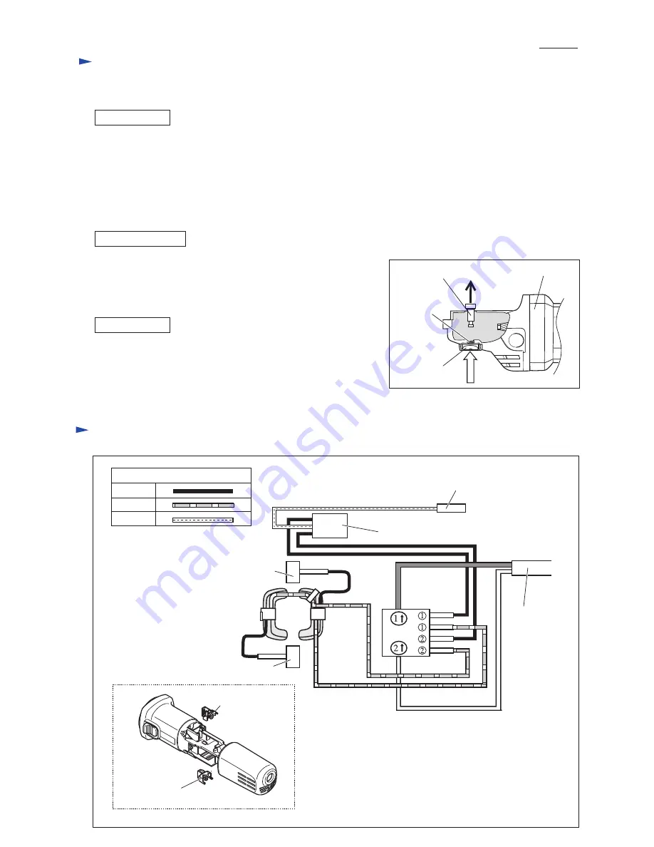
[3] -3. Disassembling/Assembling Shaft Lock Mechanism 

(1) Remove Bearing box from Gear housing.

(2) Pull off Shoulder pin 4 with pliers while pushing Pin cap with

      finger. (

Fig. 11

)

Note

: Do not pull off Shoulder pin 4 without holding Pin cap 

because Compression spring 8 would sling Pin cap.

Push Shoulder pin 4 through Gear housing and 

Compression spring 8 into Pin cap.

Note

: Do not reuse removed Pin cap because removal of Shoulder

Pin 4 damages the inside surface of Pin cap, producing plastic dust.

Therefore, be sure to use a new Pin cap for replacement and to remove

all the plastic dust on Shoulder pin 4.

DISASSEMBLING

ASSEMBLING

Fig. D-1

Fig. 11

Pin cap

Gear housing

Shoulder pin 4

Compression

spring 8 

C

ircuit diagram

Red
Clear

Color index of lead wires' sheath

Black

Brush holder A

Brush holder A

Noise suppressor*

Earth terminal (Ground terminal)

on the lead wire of Noise suppressor

Power supply

cord

Brush holder B

Brush holder B

Field

Switch

*noise suppressor is not used for some countries. 

Summary of Contents for 9556HN

Page 1: ...nput Output Max Output W 110 120 220 230 240 8 0 7 5 4 0 3 8 3 7 50 60 50 60 50 60 50 60 50 60 840 840 840 840 840 500 500 500 500 500 1 000 1 000 1 000 1 000 1 000 Current A Note The standard equipme...

Page 2: ...rasion 2 LUBRICATION Item No Description O ring 26 9 Whole portion Gear housing complete 18 a 18 a Front view Six air holes Note in Lubrication Gear housing complete of 18 b which has two air holes is...

Page 3: ...wing four 4x30 Tapping screws Fig 3 3 Remove Gear housing cover from Motor housing together with Armature by levering with a slotted screwdriver fit to the notch on the Gear housing cover Fig 4 4 Remo...

Page 4: ...ring S 12 with 1R291 then remove Wave washer 12 Spiral bevel gear large can be removed from Spindle by hand And then remove Woodruff key 4 from Spindle Fig 7 2 Remove Spindle from Bearing box using 1R...

Page 5: ...shing Pin cap with finger Fig 11 Note Do not pull off Shoulder pin 4 without holding Pin cap because Compression spring 8 would sling Pin cap Push Shoulder pin 4 through Gear housing and Compression s...

Page 6: ...n Figs D 3 D 6 Brush holder A Brush holder B Motor housing with Field view from Rear cover side Spindle Connect to Brush holder B Connect to Switch terminals Lead wire black Lead wire black Lead Wires...

Page 7: ...not used for some countries Route Lead wire of Power supply cord to Switch terminal No 2 so that it runs around boss A Motor housing Bottom view Motor housing Boss A Be sure that Field lead wires are...

Page 8: ...g is not used for some countries Sensormatic tag anti theft tag Noise suppressor Put Sensormatic tag in this space Noise suppressor Be sure that Field lead wires are tight in Motor housing Left side v...

Reviews: