W
iring diagram
P
6
/
8
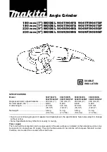
Fig. D-2
Spacer
Switch
Switch button
Power supply cord
Connect Lead wires with Switch as drawn in
Fig. D-2
.
Switch lever
Earth terminal on the lead wire (clear)
of Noise suppressor* has to be connected
to this portion.
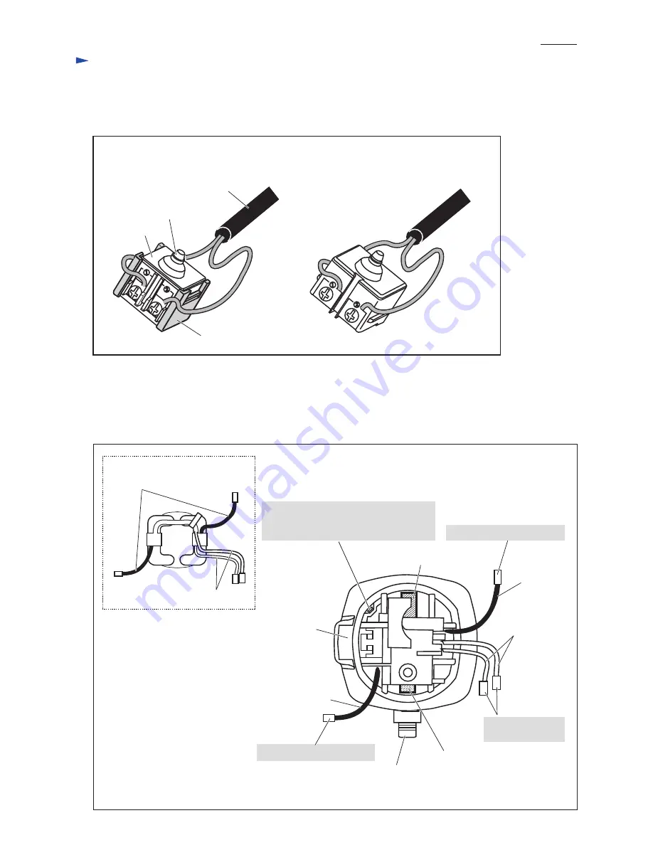
Route Field lead wires as drawn in
Figs. D-3 - D-6
.
Brush holder A
Brush holder B
[Motor housing with Field]
(view from Rear cover side)
Spindle
Connect to Brush holder B.
Connect to Switch
terminals.
Lead wire
(black)
Lead wire (black)
[Lead Wires of Field]
Fig. D-3
Lead wires (white)
Lead wires (black)
Field
Lead wire (white)
*Noise suppressor is not used for some countries.
Connect to Brush holder A.
[When Spacer is used]
[When Spacer is not used]
[4] Connecting Lead wires
[4]-1. Switch
[4] -2. Rear end of Field and Motor housing