


7 ENGLISH
NOTE:
Wait more than one second before restarting
the tool when unintentional restart proof functions.
NOTE:
When the tool is overloaded and the tool
temperature reaches a certain level, the tool may
automatically stop. In this situation, let the cool before
turning on the tool again.
Soft start feature
Soft start feature reduces starting reaction.
ASSEMBLY
CAUTION:
Always be sure that the tool is
switched off and unplugged before carrying out
any work on the tool.
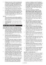
Installing side grip (handle)
CAUTION:
Always be sure that the side grip is
installed securely before operation.
Screw the side grip securely on the position of the tool
as shown in the figure.
Installing or removing wheel guard (For
depressed center wheel, flap disc, flex
wheel, wire wheel brush / abrasive cut-
off wheel, diamond wheel)
WARNING:
When using a depressed center
wheel, flap disc, flex wheel or wire wheel brush,
the wheel guard must be fitted on the tool so that
the closed side of the guard always points toward
the operator.
WARNING:
When using an abrasive cut-off
/ diamond wheel, be sure to use only the special
wheel guard designed for use with cut-off wheels.
(In some European countries, when using a diamond
wheel, the ordinary guard can be used. Follow the
regulations in your country.)
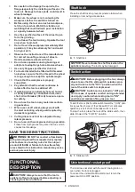
Mount the wheel guard with the protrusions on the
wheel guard band aligned with the notches on the bear-
ing box. Then rotate the wheel guard to such an angle
that it can protect the operator according to work. Be
sure to tighten the screw securely.
To remove wheel guard, follow the installation proce-
dure in reverse.
1
2
3
►
1.
Wheel guard
2.
Bearing box
3.
Screw
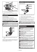
Installing or removing depressed
center wheel or flap disc
Optional accessory
WARNING:
When using a depressed center
wheel or flap disc, the wheel guard must be fitted
on the tool so that the closed side of the guard
always points toward the operator.
CAUTION:
Make sure that the mounting part
of the inner flange fits into the inner diameter of
the depressed center wheel / flap disc perfectly.
Mounting the inner flange on the wrong side may
result in the dangerous vibration.
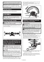
Mount the inner flange onto the spindle.
Make sure to fit the dented part of the inner flange onto
the straight part at the bottom of the spindle.
Fit the depressed center wheel / flap disc on the inner
flange and screw the lock nut onto the spindle.
1
2
4
3
►
1.
Lock nut
2.
Depressed center wheel
3.
Inner
flange
4.
Mounting part
To tighten the lock nut, press the shaft lock firmly so
that the spindle cannot revolve, then use the lock nut
wrench and securely tighten clockwise.


