background image

 4

8

R

epair

Note

: Assemble Fan 88, DC motor and Pulleys by reversing the disassembly procedure. (Refer to 

Figs. 3

and 

1

)

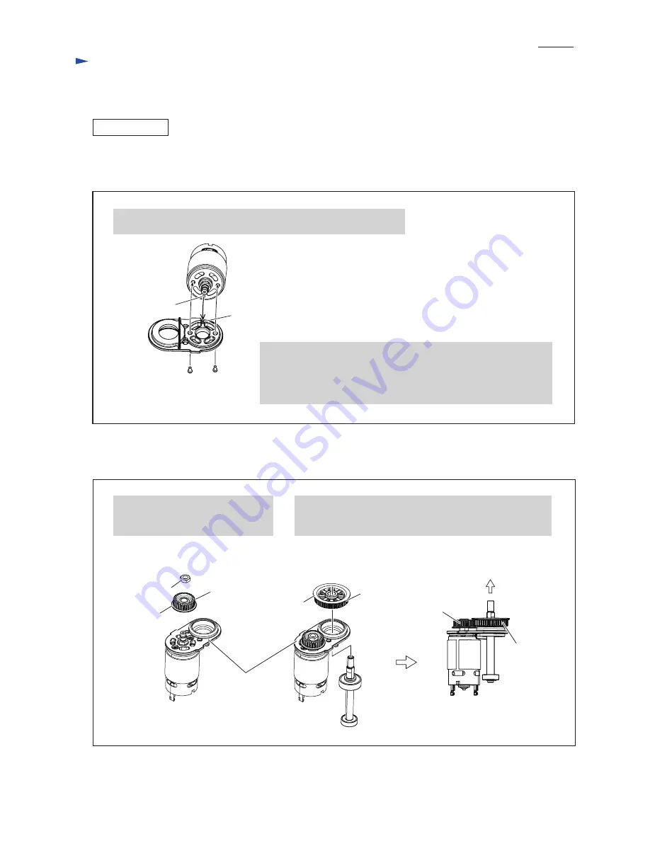
(1) Assemble DC motor to Motor bracket as drawn in 

Fig. 4

.

ASSEMBLING

(2) Assemble Pulleys as drawn in 

Fig. 5

.

1. While aligning the projection on Motor bracket to the hole of DC motor,

    mount DC Motor to Motor bracket.

Fig. 4

Fig. 5

Projection

2. Apply either of the following adhesives to the thread of M3x8 Pan 

    head screws if the same screws are reused.

      * 

ThreeBond 1342

      *  

Loctite 242


And fasten DC motor to Motor bracket with two Pan head screws.

M3x8 Pan head

screw (2 pcs.)

M6 Hex nut

Pulley 

7.5-24.1

1. Mount Pulley 7.5-24.1 to DC motor 

    while facing its brim portion to

    Motor bracket.

2. Assemble Spindle to Motor bracket.

    Then mount Pulley 7.5-40.3 to Spindle while facing its brim

    portion to the opposite side of Motor bracket. 

Brim portion

Pulley

7.5-24.1

Pulley

7.5-40.3

Fan 88 side

Motor bracket

Brim portion

Pulley 

7.5-40.3

Hole

[3] DISASSEMBLY/ASSEMBLY

[3] -1. Fan 88, DC motor and Pulleys (cont.)

Summary of Contents for BBO140

Page 1: ...nding strokes spm min Paper fastening system 7 000 9 500 11 000 14 000 19 000 22 000 Hook Loop Pad diameter mm 123 4 7 8 Abrasive disc diameter mm 125 5 18 54 1 7 3 6 BBO180 190 Model BBO140 BBO180 ha...

Page 2: ...head screws Then remove Pad 123 and Bearing box cover from Housing set Note Bearing box cover may be removed together with Pad 123 2 Remove Brake ring form Housing set 3 Unscrew M4x20 Pan head screw a...

Page 3: ...e Retaining ring S 7 with 1R291 4 Remove Ball bearing 607ZZ and Ball bearing 629DDW from Spindle 2 Remove Motor bracket from DC motor by unscrewing two M3x8 Pan head screws Fig 2 Fig 3 Fan 88 Spindle...

Page 4: ...he thread of M3x8 Pan head screws if the same screws are reused ThreeBond 1342 Loctite 242 And fasten DC motor to Motor bracket with two Pan head screws M3x8 Pan head screw 2 pcs M6 Hex nut Pulley 7 5...

Page 5: ...our notches Housing set four projections Groove on Housing set 2 First join Skirt R with Skirt L at the hinge portion And then mount Skirt R to Housing set while fitting its rib to the groove on Housi...

Page 6: ...ad wires sheath Black Red Controller unit Controller Controller AS Terminal Connector Line filter is not used for some countries Line filter is not used for some countries Line filter White Blue Yello...

Page 7: ...The Flag connector with Lead wire black has to be connected so that its wire connecting portion is located over pole mark While facing the wire connecting portions of Receptacles to Housing L side co...

Page 8: ...ide DC motor Controller While facing this cut portion to Housing L side set Switch unit to Housing L Put Line filter here Line filter is not used for some countries Fix lead wires of Connectors in the...

Reviews: