P
7
/
8
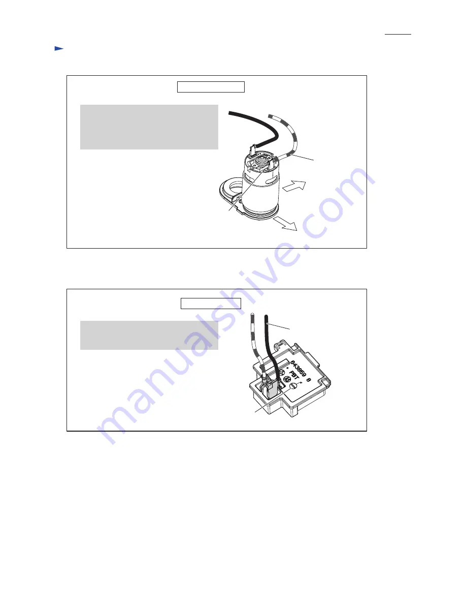
Fig. D-2
Fig. D-3
W
iring diagram
Wiring to DC motor
Wiring to Terminal
Housing L side
Red dot mark
Front side
(Switch unit side)
Lead wire (red)
The Flag connector with Lead wire (black)
has to be connected so that its wire connecting
portion is located over
(-) pole mark
.
While facing the wire connecting portions of
Receptacles to Housing L side, connect Lead
wire (red) receptacle to the terminal with
Red
dot mark
and Lead wire (black) receptacle to
the other terminal.
Lead wire (black)
(-) pole mark


