background image

R

epair

P 4 / 17 

Fig. 8

Fig. 9

Fig. 10

Fig. 11

Fig. 12

Fig. 13

Fig. 14

Ring spring 11

1R004
Retaining ring S plier

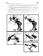
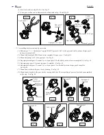
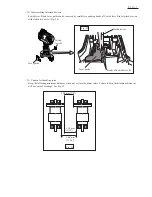
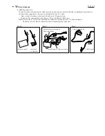
( 5 ) Mount the spindle section to clutch case as illustrated in Fig. 12.

( 6 ) Secure the spindle section in the clutch case with retaining ring R-21.  See Fig. 13.

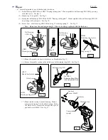
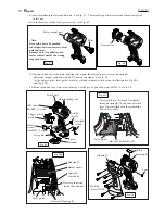
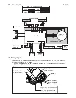
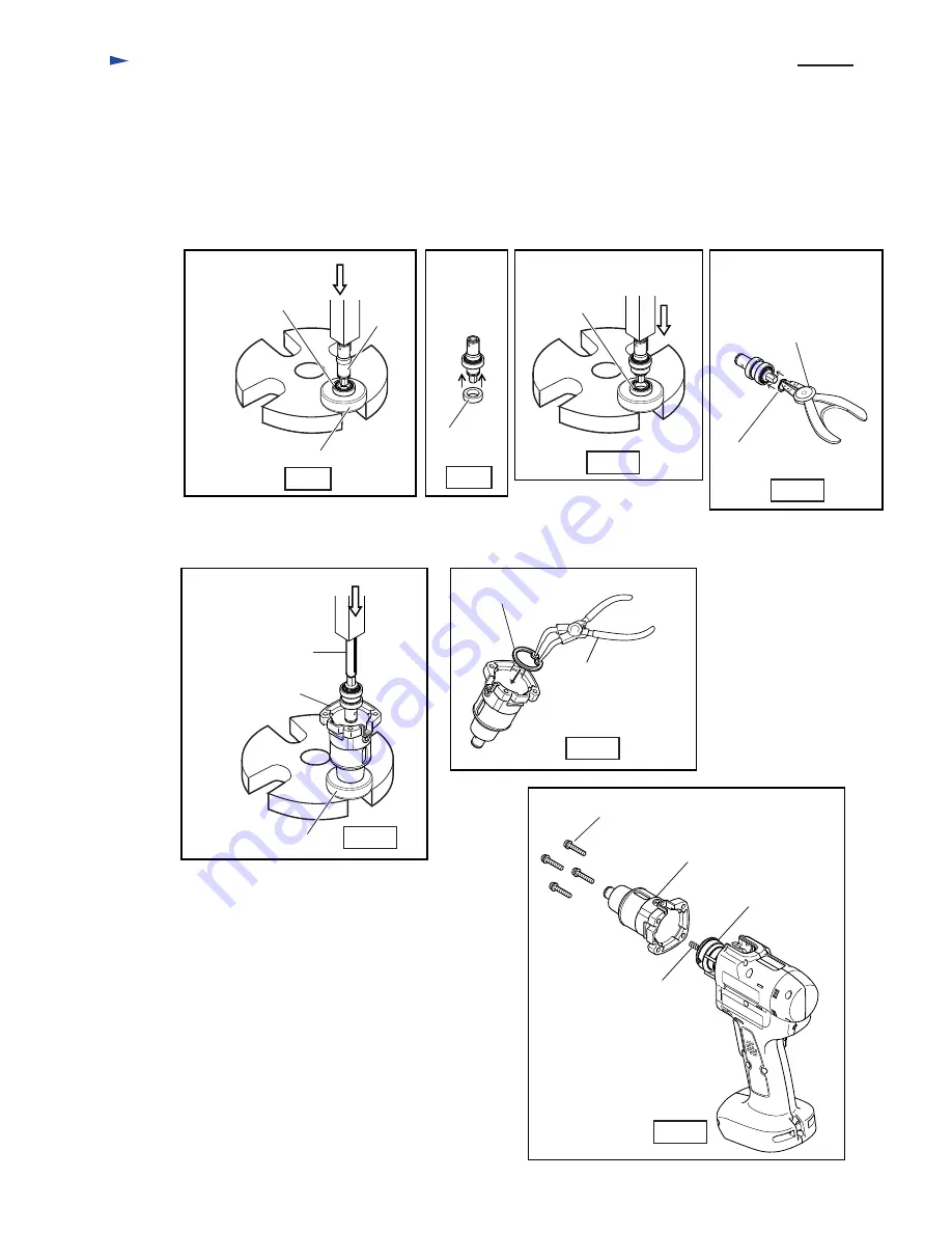
( 7 ) Mount clutch section to motor housing.  Mount 
        compression spring 5 to the clutch section. Fasten
        the clutch case to the motor housing with 4 pcs.of 
        pan head screw M4x22  See Fig. 13.

1R035
Bearing setting plate

1R036
Bearing setting plate

Ball bearing 
6801LLB

Ball bearing 
6801LLB

Spindle

Ring 12

1R237
Round bar for arbor

Clutch case

No.1R311
Retaining Ring Pliers 
with Long Bent Nails

Retaining ring R-21

Clutch case

Clutch section

Pan head
 screw M4x22

Compression 
spring 5

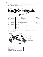
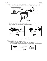
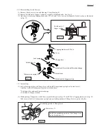
< 6 > Assembling spindle (as a bit holder) and clutch case

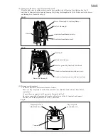
( 1 ) Set ball bearing 6801LLB on 1R035 "Bearing setting plate".  Mount spindle to ball bearing 6801LLB by pressing
        with arbor press.  See Fig. 8

( 2 ) Mount ring 12 to spindle.   See Fig. 9.

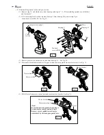
( 3 ) Set another ball bearing 6801LLB on 1R035 "Bearing setting plate".  Mount spindle to the ball bearing 6801LLB
        by pressing with arbor press.  See Fig. 10.

( 4 ) Secure 2 pcs. of ball bearing 6801LLB and ring 12 with ring spring 11.   See Fig. 11.

< Note > Do not use the used ring spring 11. It has to be always replaced with the fresh one.

Summary of Contents for BFH040

Page 1: ...rming operator of the result of fastening Battery BH1220 2 pcs Charger DC14SA 1 pc Torque adjust tool 1 pc Accessory case 1 pc Steel carrying case 1 pc Battery BH1220 Battery BH1233 Charger DC14SA Cha...

Page 2: ...gear 47 Spur gear 9 complete Carrier complete B Portion to be lubricated Amount g oz Ball bearing 6805LLB Gear case Lock washer Motor bracket Approx 2 0 08 in total Fig 2 Fig 1 2 Disassembling bit hol...

Page 3: ...See Fig 5 4 Remove ring spring 11 from spindle And then remove ball bearing 6801LLB on the ring spring 11 side See Fig 6 5 After removing ring 12 remove the another ball bearing 6801lLB See Fig 7 Not...

Page 4: ...indle Ring 12 1R237 Round bar for arbor Clutch case No 1R311 Retaining Ring Pliers with Long Bent Nails Retaining ring R 21 Clutch case Clutch section Pan head screw M4x22 Compression spring 5 6 Assem...

Page 5: ...as a bit holder and clutch case 2 Remove clutch section from motor housing See Fig 17 Clutch section Compression spring 5 4 Remove adjust ring complete flat washer 18 and compression spring 19 from sp...

Page 6: ...head screw M5x10 Torx counter sunk head screw M5x10 Hex wrench Torx wrench T25 6mm Steel balls 3 0 13 pcs Flat washer 7 Cam A Note Pay attention not to lose steel balls when disassembling Use the hex...

Page 7: ...cam D to spindle with aligning its 3 grooves with steel balls 5 Mount steel balls 4 to cam B Mount cam A Cam B Steel balls 4 3 pcs Steel balls 3 0 13 pcs Mount steel balls 3 0 to cam A Mount flat was...

Page 8: ...th motor section from housing R 4 Turn motor bracket anti clockwise So gear section can be separated from motor section See Fig 35 5 Pull off rotor from motor control unit and remove motor bracket See...

Page 9: ...Fig 40 3 Mount internal gear 47 to the gear case See Fig 41 4 Engaging internal gear 47 mount 3 pcs of spur gear 18 to the shaft portion of carrier complete B See Fig 42 5 Engaging spur gears 18 mount...

Page 10: ...ing R See Fig 49 12 Mount plate and lens And secure housing L with 8 pcs of pan head screw M3x20 See Fig 50 Pan head screws M3x20 Housing L Housing R Plate Lens Switch unit Plate installing side Space...

Page 11: ...parts in place on Switch base Compression spring 4 Switch lever A Change lever Leaf spring Switch unit for rotational direction change Switch base Switch unit of trigger section Tapping bind screw PT...

Page 12: ...54 Hooks of Switch lever B Lever guide Slotted driver Fig 54 Fig 55 12 Disassembling Interlock Section 13 Caution fort handling rotor Keep the following minimum distances when put or store the plural...

Page 13: ...tors be sure to connect together two Connectors that have lead wires of the same colors 1 Wiring in the rotor fan side of housing Set Motor section in place on Housing R and then as illustrated in Fig...

Page 14: ...ire to Motor control unit yellow 3 Lead wire to Motor control unit purple 4 Lead wire from LED circuit gray 5 Lead wire from LED circuit blue 6 Lead wire to Motor control unit gray 7 Lead wire to Moto...

Page 15: ...lace the lead wires from Buzzer between the boss and the wall of Housing R as illustrated in Fig D And then fix Interlock switch unit to Housing R by fitting the through holes of the Switch unit to th...

Page 16: ...er them Fig G Fig H Red lead wire which connects Terminal to Motor control unit And black one Terminal Note Make sure that spacer has been mounted to housing R before setting terminal Refer to Fig 49...

Page 17: ...rlock switch unit Switch unit of Trigger section Switch unit for rotational direction change Clutch switch unit LED circuit Note Never hold the wires when separating the connectors because they are ve...

Reviews: