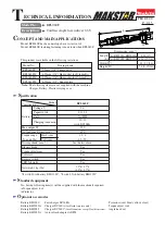


BFL060F
Cordless Angle Screwdriver 9.6V
Model No.
Description
PRODUCT
T
ECHNICAL INFORMATION
C
ONCEPT AND MAIN APPLICATIONS
S
pecification
S
tandard equipment
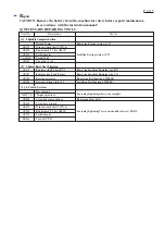
O
ptional accessories
P 1/15
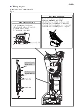
W
H
L
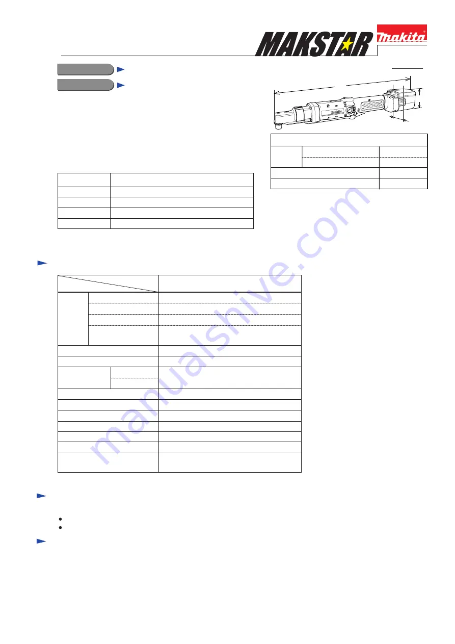
Dimensions: mm (")
Width (W)
Height (H)
Length
(L)
w/ BH 9033, BH9033A
w/ BH 9020, BH9020A
430 (17)
454 (17-7/8)
74 (2-15/16)
65 (2-9/16)
Model BFL060F has been developed as a sister tool of
Model BFL080F, featuring fastening torque lower than BFL080F.
This product is available in the following variations.
Model No.
Driving shank
BFL060F2Z
6.35mm (1/4") Hex socket for C-form Bit
BFL060F1Z
6.35mm (1/4") Hex socket for E-form Bit
BFL060FZ
9.5mm (3/8") Square drive
BFL060F5Z
6.35mm (1/4") Square drive
BFL060F
Model
Specifications
No load speed: rpm= min
-1
450
15/ 22
with DC18RA
150
1.5*
1
/ 1.7*
2
(3.3*
1
/ 3.7*
2
)
Battery
Driving shank: mm (")
Net weight: kg (lbs)
LED Job light
Torque adjustment
Torque range:
N.m (in.lbs)
1.5 - 6
(13 - 53)
Hard joint
Soft joint
Yes
Yes
See the list above.
Electric brake
Soft start
Yes
Reverse switch
Yes
Yes
Cell
Charging time: min.
Voltage: V
Capacity: Ah
Ni-MH
9.6
2.0/ 3.3
Max output: W
*1 with 2.0Ah battery BH1220C, *2 with 3.3Ah battery BH1233C
No, but the following item(s) will be supplied with the machine if required:
Torque adjust tool
Protector
Battery BH9020
Battery BH9020A
Battery BH9033
Battery BH9033A
Fast charger DC18RA
Charger DC24SA
(for North America only)
Charger DC24SC
(for all countries except North America)
Auto refresh adapter ADP03
Protectors (red/ blue/ yellow/ clear)
Torque adjust tool
Angle head set
Note: The following items are not supplied with the machine:
Charger, Battery, Plastic carrying case


