
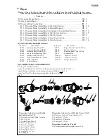


P 13/ 13
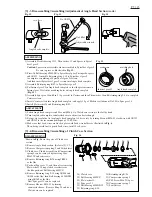
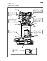
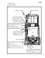
Fig. 31
W
iring diagram
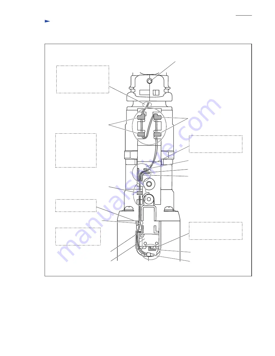
tab
rib (J)
rib (I)
rib (H)
Route the lead wires between
rib (H) and rib (I), and then
rib (I) and rib (J).
Put Connector and the sag
of the lead wires in the space
between Housing and rib (L).
LED circuit
tab
tab
Make the lead wires so that
they cannot be pulled to
disconnect LED circuit from
Controller when Switch
cover is installed.
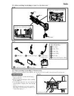
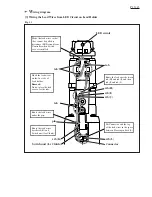
[3] Wiring the Lead Wires from LED Circuit on Lead Holder
Connector
Switch unit (for Clutch)
rib (L)
rib (K)
Route the lead wires
under the pin.
Hook the lead wires
on the five tabs of
Lead holder.
Remark:
Do not place the lead
wires over the tabs.
Route the lead wires
beside rib (K) and
Switch unit (for Clutch).
pin


