W
iring diagram
P 13 / 15
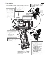
Wiring in housing (9.6V models BFT040F, BFT080F and BFT122F )
Pass the endbell lead wires (black and
red) both sides of LED cover portion
of controller.
LED cover
portion
Endbell
lead wire
(black)
Endbell lead
wire (red)
Pass the following lead wires
between the ribs of switch.
* Controller's lead wires (white
and orange) to be connected
to micro switch.
* Controller's lead wires (blue,
purple and white) to be
connected to reverse switch.
* Controller's lead wires (red
and white) to be connected
to buzzer circuit.
Connector
Terminal
Buzzer circuit has to be so mounted,
that the sponge side is faced to the
housing L side.
The connector has to be put
on the terminal side of this line
as illustrated.
Pass the following lead wires
between rib and the wall of
housing.
* Terminal lead wires
(black and red)
* Buzzer circuit lead wires
(white and red)
Buzzer
circuit
LED circuit
Controller
Switch unit
Switch
Rib
Rib
Pay attention, not to pinch the
above lead wires between switch
and housing.
Put the following lead
wires out of housing.
* Controller lead wires
(gray and blue) for
connecting to LED
circuit
* Controller lead wires
(purple and yellow) for
connecting to switch
unit
Refer to "Wiring on the
switch unit" in detail
on the page 15.
Refer to "Wiring on the
switch" in detail on the
page 15.
1
2


