W
iring diagram
P 15 / 15
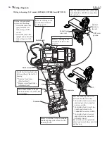
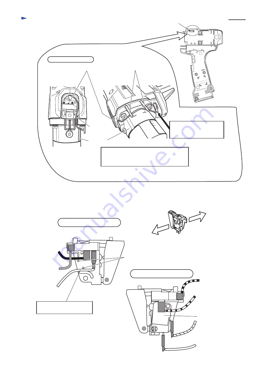
1. Wiring on the switch unit (BFT040F, BFT080F, BFT122F, BFT123F)
2. Wiring on the switch (BFT040F, BFT080F, BFT122F, BFT123F)
Switch unit
Top view of switch unit
Switch unit
Pass the lead wires, covered by shrink tube,
through the pin.
And hold them with lead holders at clutch case.
Clutch case
Lead holder
Contain the slack portion
of lead wires and connectors
into this pace.
Controller lead
wire (white)
Controller lead
wire (white)
Controller lead
wire (purple)
Controller lead
wire (orange)
Controller lead
wire (blue)
Endbell lead
wire (black)
Endbell lead
wire (red)
View from micro switch side
Micro switch
Lead holder
Hold the controller lead
wire (white) with lead holder.
View from ON/OFF switch side
ON/OFF
switch side
Micro
switch side
Pin


